
CONTROL SYSTEM - Engine Control Unit Inspection
F-127prose procedureENGINE CONTROL UNIT
Inspection
Engine Control Unit Inspection
- 1Lift up the floormat in front of the passenger's seat.
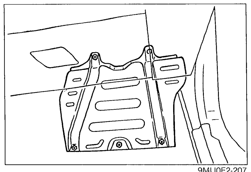 9MU0F2-207
 - 2Remove the protector cover.
- 3Connect the Engine Signal Monitor between the engine control unit and the wiring harness using the Adapter as shown.
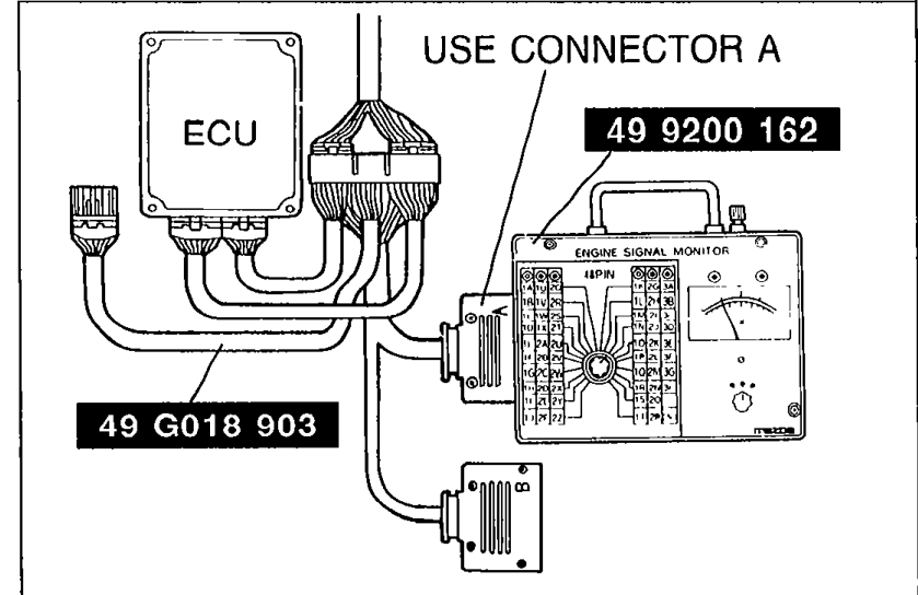 05U0FX-199
 - 4Place the SST (Sheet) on the SST.
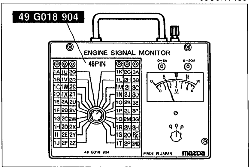 05U0FX-234
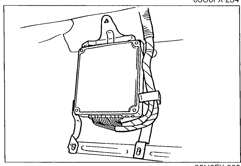
 - 5Measure the voltage at each terminal. (Refer to pages F-128 to F-130.)
- 6If any engine control unit terminal voltage is incorrect, check the input or output device and related wiring. If they are normal, replace the engine control unit. (Refer to pages F-131 to F-133.)Never apply voltage to SST terminals A and B.
 05U0FX-200
CAUTION
Never apply voltage to SST terminals A and B.
See also
F-129CONTROL SYSTEM - Engine Control Unit Terminal Voltage Table (continued)F-130CONTROL SYSTEM - Engine Control Unit Terminal Voltage / Terminal locationF-131CONTROL SYSTEM - Check Point for Each TerminalF-132CONTROL SYSTEM - Check Point for Each Terminal (continued)F-133CONTROL SYSTEM - Check Point for Each Terminal (continued)