Mazda MX-5 NA silhouetteMX-5 NA

ENGINE STAND MOUNTING

B-34parts diagram

PROCEDURE

Engine Stand Mounting

  1. 1
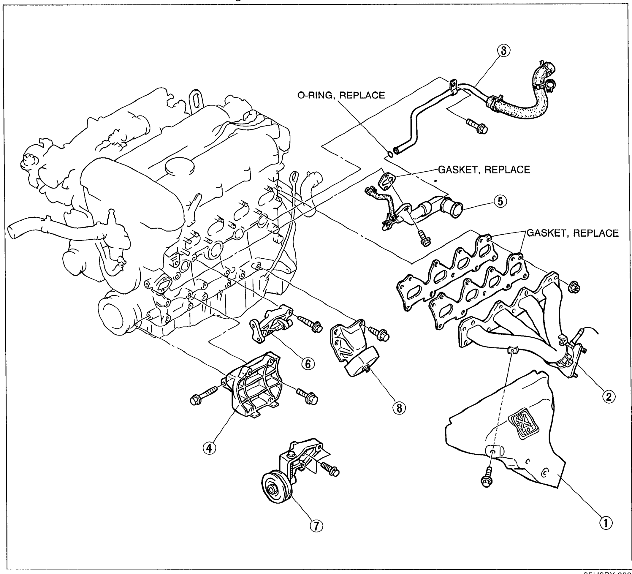
    Remove in the order shown in the figure.
    O-RING, REPLACE
    GASKET, REPLACE (water inlet pipe area)
    GASKET, REPLACE (exhaust manifold)
    Exploded view of engine accessories to remove before stand mounting. Shows the engine with eight numbered balloon callouts pointing to: exhaust manifold insulator (1), exhaust manifold (2), water bypass pipe (3), A/C compressor bracket (4), water inlet pipe (5), P/S oil pump bracket (6), idler A/C (7), left engine mount (8). 'O-RING, REPLACE' and 'GASKET, REPLACE' replacement notes are labeled with arrows.
    05U0BX-083
  2. 2
    When installing the SST (engine hanger), use the holes shown in the figure.
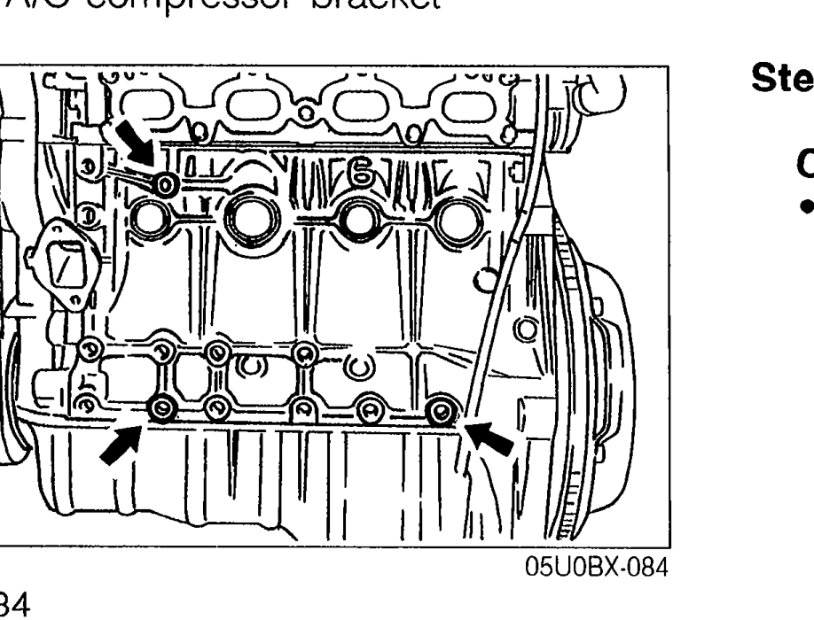
    When installing the SST (engine hanger), use the holes shown in the figure.
    Top view of the engine showing the SST (engine hanger) mounting holes for Step 2, with arrows pointing to the hole locations.
    05U0BX-084
Parts DiagramFig. fig1
#Part NameNotes
1Exhaust manifold insulator
2Exhaust manifold
3Water bypass pipe
4A/C compressor bracket
5Water inlet pipe
6P/S oil pump bracket
7Idler (A/C)
8Left engine mount

Search Manual

Search pages, specs, and procedures