
INSPECTION / REPAIR
B-49prose procedureCylinder head — manifold contact surface
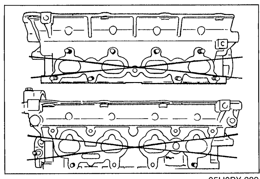
- 4Measure the manifold contact surface distortion in the four directions shown in the figure.
 05U0BX-289
 - 5If distortion exceeds specification, grind the surface or replace the cylinder head.
| Specification | Value |
|---|---|
| DistortionManifold contact surface | 0.15mm (0.006 in) max |
DistortionManifold contact surface
0.15mm (0.006 in) max
VALVE MECHANISM
Valve and valve guide
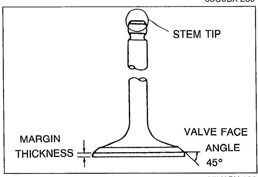
- 1Inspect each valve for the following. Replace or resurface the valve if necessary. (1) Damaged or bent stem. (2) Rough or damaged face. (3) Damaged or unevenly worn stem tip.
 05U0BX-122
 - 2Measure the valve head margin thickness of each valve. Replace the valve if necessary.
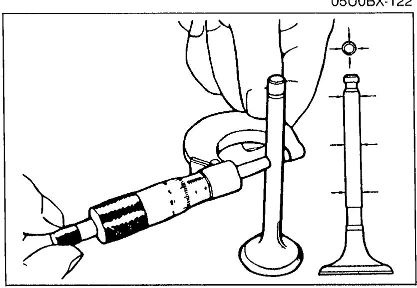
- 3Measure the length of each valve at the points shown.
 05U0BX-123
 - 4Measure the stem diameter of each valve.
 05U0BX-124
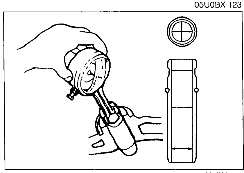
 - 5Measure the inner diameter of each valve guide at the points shown.
- 6Calculate the valve stem to guide clearance. Subtract the outer diameter of the valve stem from the inner diameter of the corresponding valve guide.
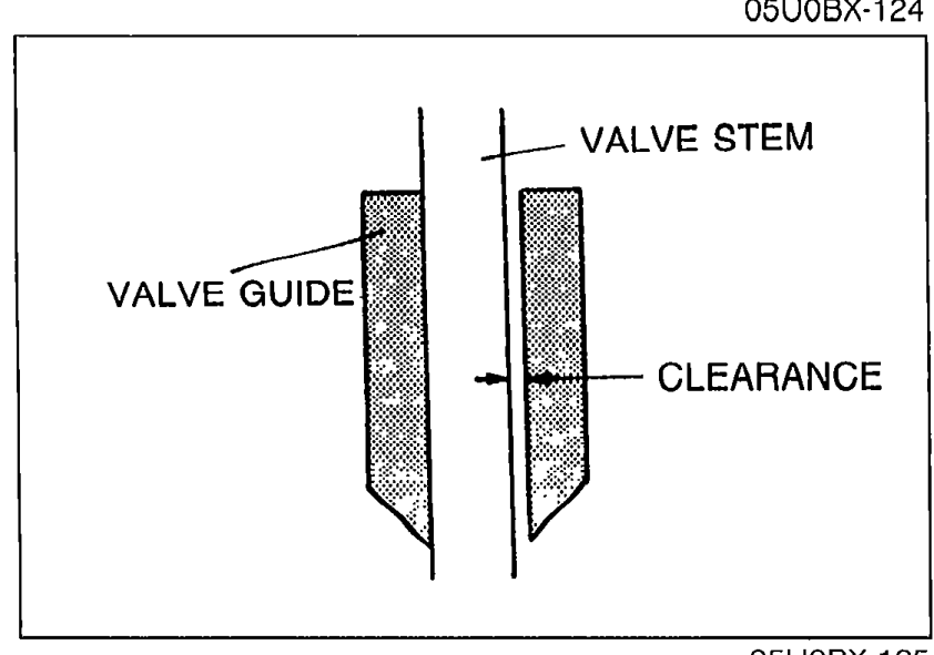 05U0BX-125
 - 7If the clearance exceeds specification, replace the valve and/or valve guide.
| Specification | Value |
|---|---|
| Margin thickness INIntake valve | 1.0mm (0.039 in) |
| Margin thickness EXExhaust valve | 1.0mm (0.039 in) |
| Length — Standard INIntake valve | 105.29mm (4.1452 in) |
| Length — Standard EXExhaust valve | 105.39mm (4.1492 in) |
| Length — Minimum INIntake valve | 104.79mm (4.1256 in) |
| Length — Minimum EXExhaust valve | 104.89mm (4.1295 in) |
| Stem diameter INIntake valve | 5.970—5.985mm (0.2350—0.2356 in) |
| Stem diameter EXExhaust valve | 5.965—5.980mm (0.2348—0.2354 in) |
| Valve guide inner diameter INIntake | 6.01—6.03mm (0.2366—0.2374 in) |
| Valve guide inner diameter EXExhaust | 6.01—6.03mm (0.2366—0.2374 in) |
| Stem-to-guide clearance INIntake | 0.025—0.060mm (0.0010—0.0024 in) |
| Stem-to-guide clearance EXExhaust | 0.030—0.065mm (0.0012—0.0026 in) |
| Stem-to-guide clearance MaximumWear limit | 0.20mm (0.008 in) |
Margin thickness INIntake valve
1.0mm (0.039 in)
Margin thickness EXExhaust valve
1.0mm (0.039 in)
Length — Standard INIntake valve
105.29mm (4.1452 in)
Length — Standard EXExhaust valve
105.39mm (4.1492 in)
Length — Minimum INIntake valve
104.79mm (4.1256 in)
Length — Minimum EXExhaust valve
104.89mm (4.1295 in)
Stem diameter INIntake valve
5.970—5.985mm (0.2350—0.2356 in)
Stem diameter EXExhaust valve
5.965—5.980mm (0.2348—0.2354 in)
Valve guide inner diameter INIntake
6.01—6.03mm (0.2366—0.2374 in)
Valve guide inner diameter EXExhaust
6.01—6.03mm (0.2366—0.2374 in)
Stem-to-guide clearance INIntake
0.025—0.060mm (0.0010—0.0024 in)
Stem-to-guide clearance EXExhaust
0.030—0.065mm (0.0012—0.0026 in)
Stem-to-guide clearance MaximumWear limit
0.20mm (0.008 in)