
ON-VEHICLE MAINTENANCE — HLA Removal / Installation
B-20parts diagramHLA
Removal / Installation
CAUTION
Obtain the code number and deactivate the audio anti-theft system before disconnecting the battery. (Refer to page T-113.) Position the hose clamp in the original location on the hose, and squeeze the clamp lightly with large pliers to ensure a good fit.
HLA Removal / Installation
- 1Disconnect the negative battery cable.
- 2Drain the engine coolant.
- 3Remove in the order shown in the figure, referring to Removal Note.
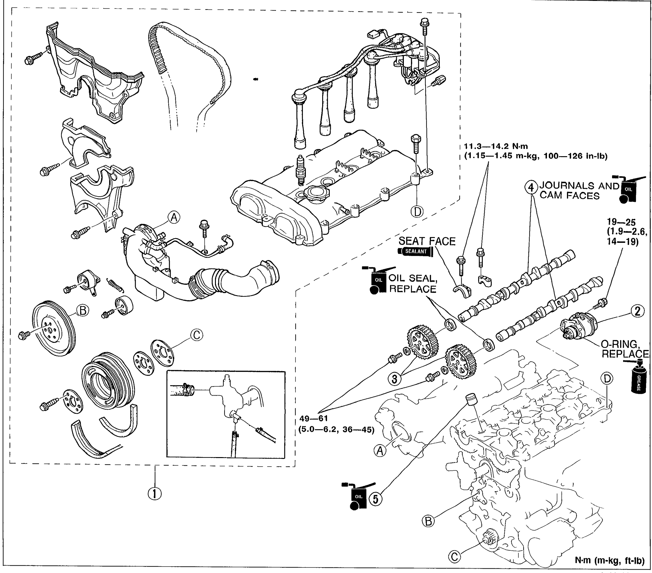 05U0BX-047
 - 4Install in the reverse order of removal, referring to Installation Note.
Parts DiagramFig. fig1
| Specification | Value |
|---|---|
| Torque (camshaft cap / cover area) | 11.3 - 14.2N·m |
| Torque (camshaft pulley bolt area) | 49 - 61N·m |
| Torque (crank angle sensor area) | 19 - 25N·m |
Torque (camshaft cap / cover area)
11.3 - 14.2N·m
Torque (camshaft pulley bolt area)
49 - 61N·m
Torque (crank angle sensor area)
19 - 25N·m