Mazda MX-5 NA silhouetteMX-5 NA

ENGINE STAND MOUNTING

B-35prose procedure

Engine Stand Mounting (continued)

  1. 1
    Install the SST (arms) to the holes as shown in the figure, and loosely tighten the SST (bolts).
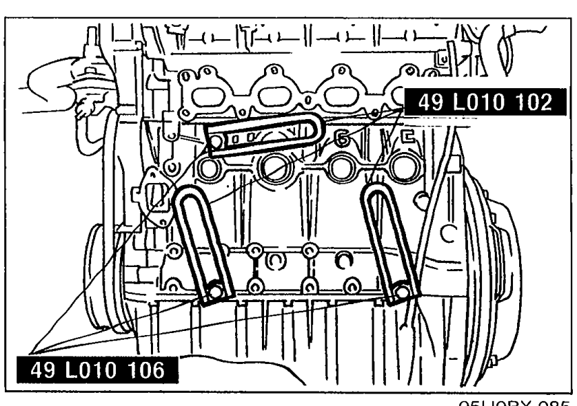
    Top view of cylinder head showing the SST arms (49 L010 102 and 49 L010 106) installed in the engine mounting holes.
    05U0BX-085
  2. 2
    Assemble the SST (bolts and plate) in the specified position.
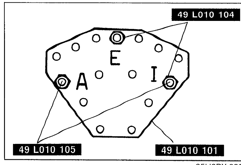
    SST bolts and plate assembly. The plate has letters 'A' and 'I' marked on it indicating bolt-hole positions. Tool numbers shown: 49 L010 104 (top), 49 L010 105 (bottom-left), 49 L010 101 (bottom-right).
    05U0BX-086
  3. 3
    Assemble the SST (nuts, hooks, and bolts).
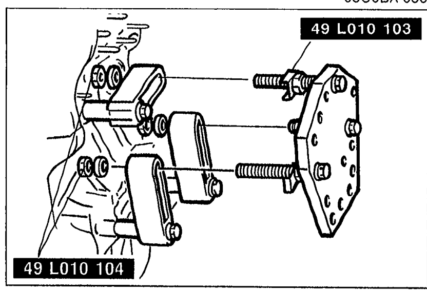
    Assembly view of SST nuts, hooks, and bolts attaching the SST plate to the arms. Tool numbers shown: 49 L010 103 (top) and 49 L010 104 (bottom).
    05U0BX-087
  4. 4
    Install the SST to the respective arms.
  5. 5
    Tighten the SST (bolts and nuts) to affix the SST firmly.
    Adjust the SST (bolts) so that less than 20mm (0.79 in) of thread is exposed.
    Make the SST (plate and arms) parallel by adjusting the SST (bolts and nuts).
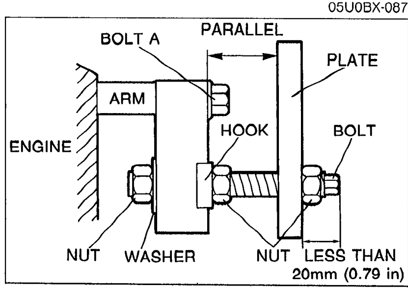
    Schematic showing the SST bolt adjustment detail with labeled components: ENGINE, ARM, HOOK, PLATE, BOLT A, PARALLEL alignment, BOLT, NUT, WASHER. Annotation 'LESS THAN 20mm (0.79 in)' indicates the maximum bolt thread exposure allowed.
    05U0BX-088
  6. 6
    Mount the engine on the SST (engine stand).
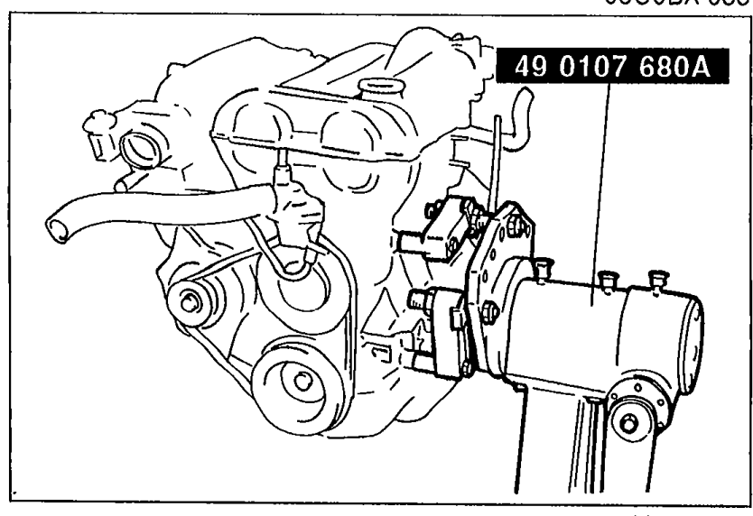
    Engine mounted on the SST engine stand (49 0107 680A). Shows the engine attached to the SST with the support arms and plate.
    05U0BX-089

Search Manual

Search pages, specs, and procedures