
INSPECTION / REPAIR
B-57prose procedurePiston ring end gap
- 5Measure each piston ring end gap with a feeler gauge. Replace the piston ring if necessary.
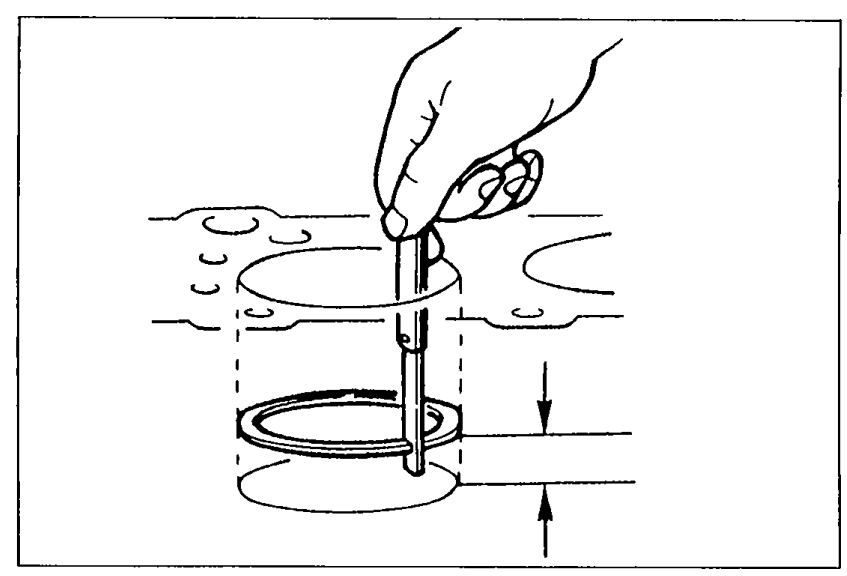 05U0BX-158
| Specification | Value |
|---|---|
| End gap — Topstandard | 0.15—0.30 mm (0.006—0.012 in)mm |
| End gap — Secondstandard | 0.15—0.30 mm (0.006—0.012 in)mm |
| End gap — Oil railstandard | 0.20—0.70 mm (0.008—0.028 in)mm |
| Maximummaximum | 1.0 mm (0.039 in)mm |
End gap — Topstandard
0.15—0.30 mm (0.006—0.012 in)mm
End gap — Secondstandard
0.15—0.30 mm (0.006—0.012 in)mm
End gap — Oil railstandard
0.20—0.70 mm (0.008—0.028 in)mm
Maximummaximum
1.0 mm (0.039 in)mm
Piston and Piston Pin
Piston pin hole measurement
- 1Measure each piston pin hole diameter in X and Y directions at four points.
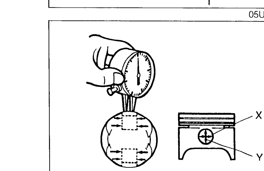 05U0BX-159
| Specification | Value |
|---|---|
| Diameterstandard | 19.988—20.000 mm (0.7869—0.7874 in)mm |
Diameterstandard
19.988—20.000 mm (0.7869—0.7874 in)mm
Piston pin diameter and clearance
- 2Measure each piston pin diameter in X and Y directions at four points.
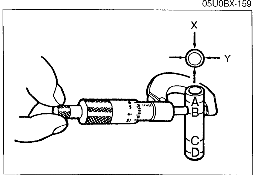 05U0BX-160
 - 3Calculate the piston pin-to-piston clearance.
- 4If the clearance exceeds specification, replace the piston and/or piston pin.
| Specification | Value |
|---|---|
| Diameterstandard | 19.987—19.993 mm (0.7869—0.7871 in)mm |
| Clearancestandard | -0.005—0.013 mm (-0.0002—0.0005 in)mm |
Diameterstandard
19.987—19.993 mm (0.7869—0.7871 in)mm
Clearancestandard
-0.005—0.013 mm (-0.0002—0.0005 in)mm
CONNECTING ROD
Connecting rod inspection
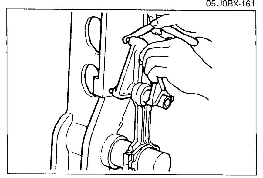
- 1Measure each connecting rod bushing inner diameter.
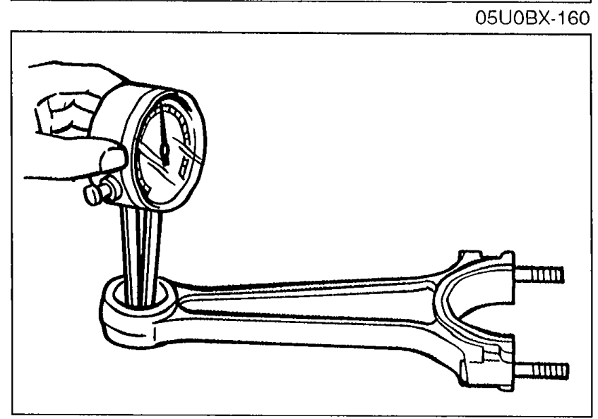 05U0BX-161
 - 2Calculate the clearance between the connecting rod bushing and piston pin.
- 3Measure each connecting rod for bending. Repair or replace the connecting rod if necessary.
 05U0BX-162
| Specification | Value |
|---|---|
| Diameterbushing inner | 20.003—20.014 mm (0.7875—0.7880 in)mm |
| Clearancebushing-to-pin | 0.010—0.027 mm (0.0004—0.0011 in)mm |
| Bendingmax. per 50 mm | 0.075 mm (0.0030 in) max./50 mm (1.97 in)mm |
Diameterbushing inner
20.003—20.014 mm (0.7875—0.7880 in)mm
Clearancebushing-to-pin
0.010—0.027 mm (0.0004—0.0011 in)mm
Bendingmax. per 50 mm
0.075 mm (0.0030 in) max./50 mm (1.97 in)mm