Mazda MX-5 NA silhouetteMX-5 NA

INSTALLATION

B-87prose procedure

Step 3

Step 3 — Connect hoses

  1. 1
    Connect the hoses shown in the figure.
    Caution: Position the hose clamp in the original location on the hose, and squeeze the clamp lightly with large pliers to ensure a good fit.
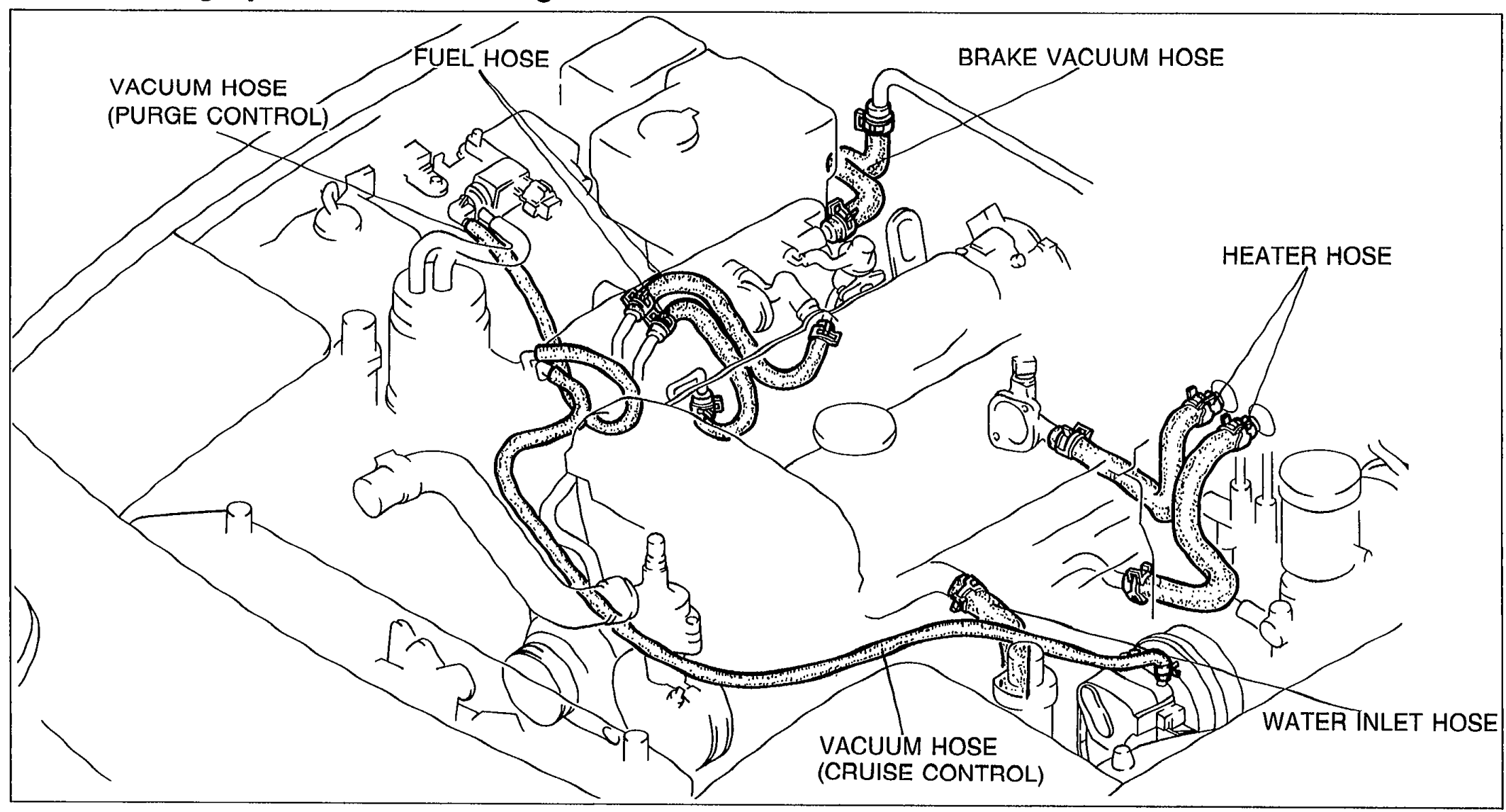
    Top view of the engine showing hose routing with leader-line callouts: VACUUM HOSE (PURGE CONTROL), FUEL HOSE, BRAKE VACUUM HOSE, HEATER HOSE, WATER INLET HOSE, and VACUUM HOSE (CRUISE CONTROL).
    05U0BX-267

Step 4

Step 4 — Connect harness connectors

  1. 1
    Connect the harness connectors shown in the figure.
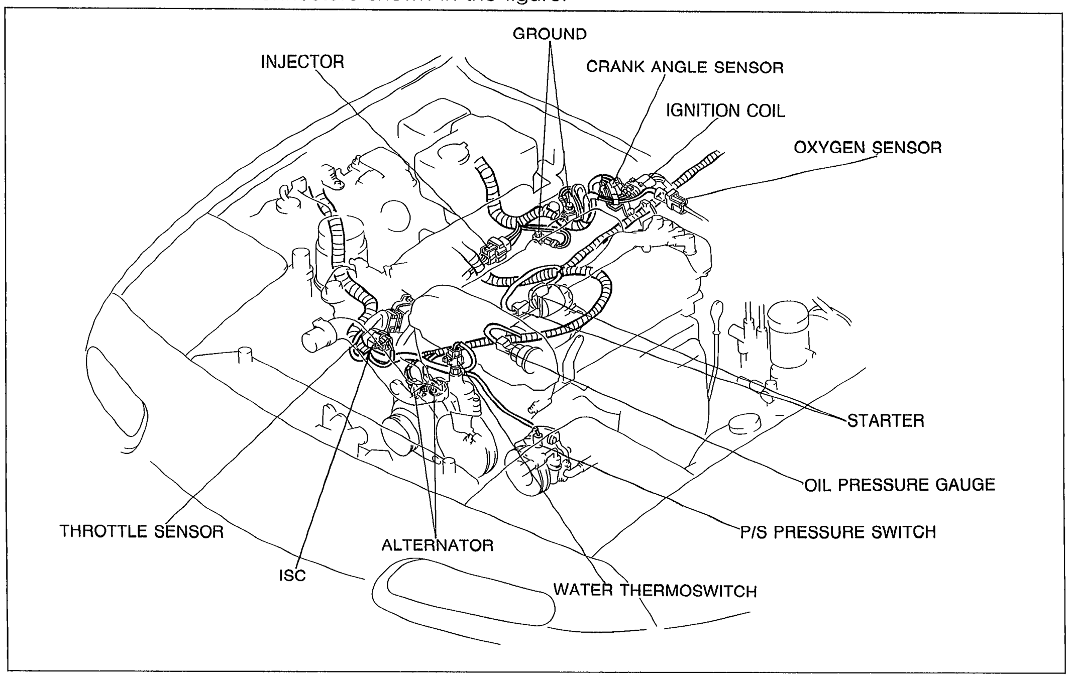
    Top view of the engine bay showing harness-connector locations with leader-line callouts: INJECTOR, GROUND, CRANK ANGLE SENSOR, IGNITION COIL, OXYGEN SENSOR, STARTER, OIL PRESSURE GAUGE, P/S PRESSURE SWITCH, WATER THERMOSWITCH, ALTERNATOR, ISC, and THROTTLE SENSOR.
    05U0BX-268

Search Manual

Search pages, specs, and procedures