
ASSEMBLY
B-65prose procedurePiston and Connecting Rod Assembly
CAUTION
Protect the connecting rod bolts with rubber sleeves to prevent damage to the crankpin journals.
Piston and Connecting Rod Installation
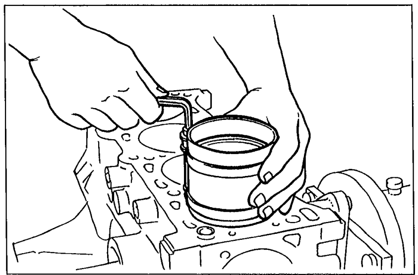
- 1Apply a liberal amount of clean engine oil to the cylinder walls, pistons, and piston rings.
 05U0BX-193
 - 2Check the piston rings for correct end gap alignment.
- 3Insert each piston assembly into the cylinder block with the F mark facing the front of the engine. Use a piston ring compressor (commercially available).
Connecting Rod Cap
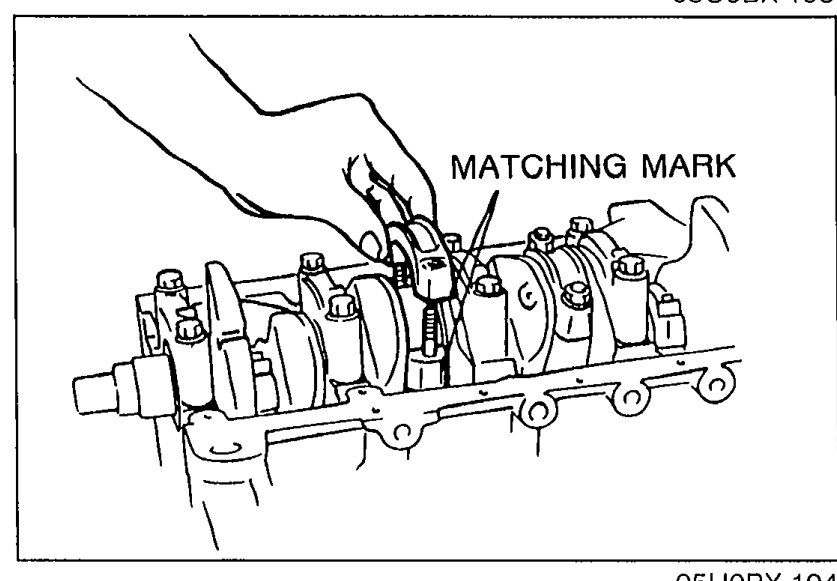
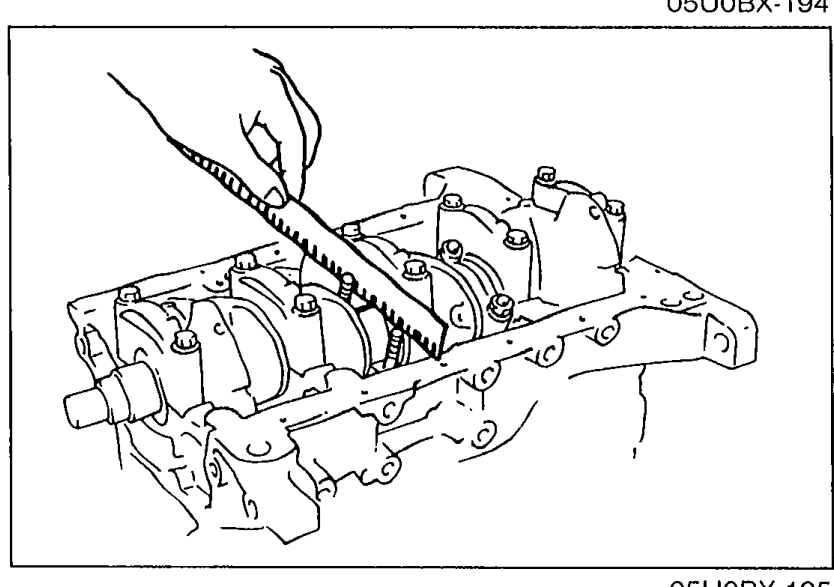
- 1Measure the connecting rod bearing oil clearances using the same procedure as for the main bearing oil clearance.
 05U0BX-194
CAUTION
Align the matching marks on the cap and the connecting rod when installing the connecting rod cap.
| Specification | Value |
|---|---|
| connecting rod cap | ≈490 - 530N·m |
connecting rod cap
490 - 530N·m
| Specification | Value |
|---|---|
| Oil clearance | 0.028—0.068mm (0.0011—0.0027 in) |
| Maximum | 0.10mm (0.004 in) |
Oil clearance
0.028—0.068mm (0.0011—0.0027 in)
Maximum
0.10mm (0.004 in)
Connecting Rod Cap (continued)
- 2If the oil clearance exceeds the maximum, grind the crankshaft and use undersize bearings. (Refer to page B-58.)
 05U0BX-195
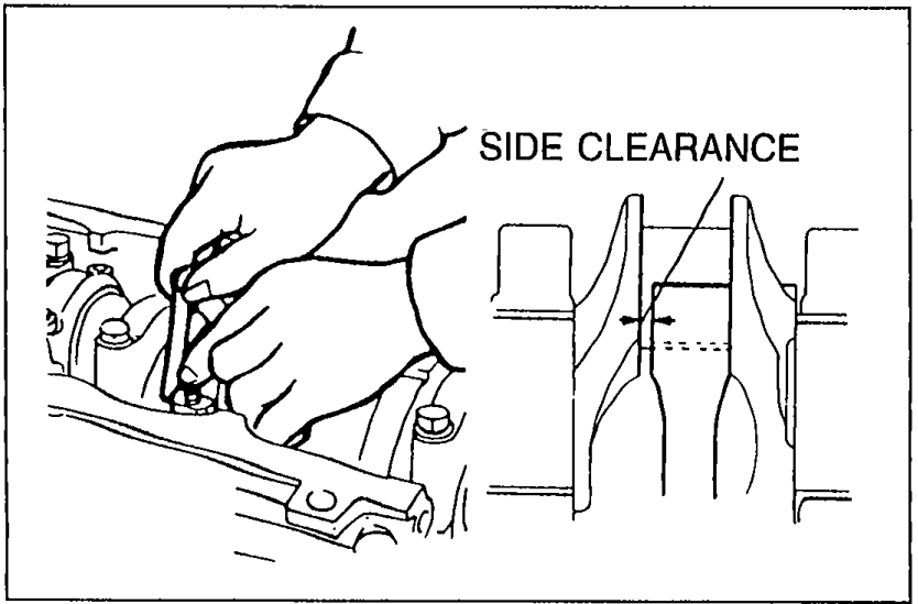
 - 3Measure the connecting rod side clearances.
 05U0BX-196
| Specification | Value |
|---|---|
| Side clearance | 0.110—0.262mm (0.0043—0.0103 in) |
| Maximum | 0.30mm (0.012 in) |
Side clearance
0.110—0.262mm (0.0043—0.0103 in)
Maximum
0.30mm (0.012 in)
Connecting Rod Cap (continued)
- 4If the clearance exceeds the maximum, replace the connecting rod and cap.