
INSPECTION / REPAIR
B-50prose procedureValve guide height
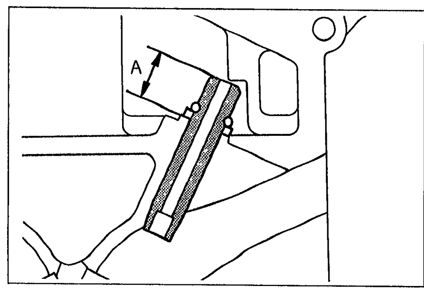
- 8Measure the height A of each valve guide. Replace the valve guide if necessary.
 05U0BX-126
| Specification | Value |
|---|---|
| Height AValve guide | 16.8—17.4mm (0.661—0.685 in) |
Height AValve guide
16.8—17.4mm (0.661—0.685 in)
Replacement of valve guide
NOTE
• Although the shapes of the intake and exhaust valve guides are different, use the exhaust valve guide on both sides as a replacement.
Removal
Valve guide removal
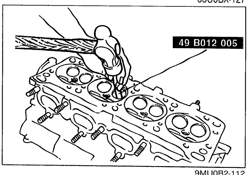
- 1Remove the valve guide from the side opposite the combustion chamber with the SST.
 9MU0B2-112
Installation
Valve guide installation
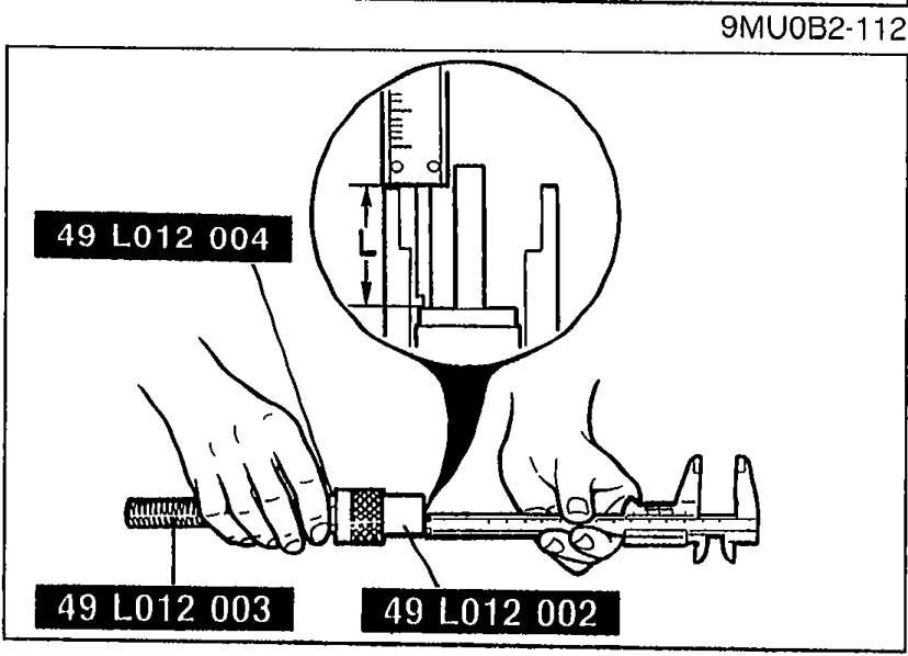
- 1Assemble the SST so that depth L is as specified.
 05U0BX-128
 - 2Tighten the locknut.
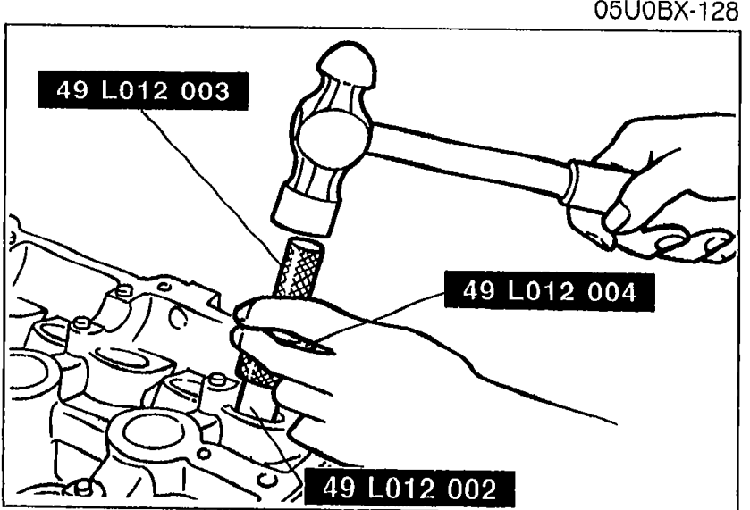
- 3Tap the valve guide in from the side opposite the combustion chamber until the SST contacts the cylinder head.
 05U0BX-129
 - 4Verify that the valve guide height is within specification.
- 5If not within specification, repeat Steps 1—4.
| Specification | Value |
|---|---|
| Depth LValve guide installation | 16.8—17.4mm (0.661—0.685 in) |
Depth LValve guide installation
16.8—17.4mm (0.661—0.685 in)