
CRUISE CONTROL SYSTEM
T-101prose procedureStep 7 — Inspection of stoplight switch
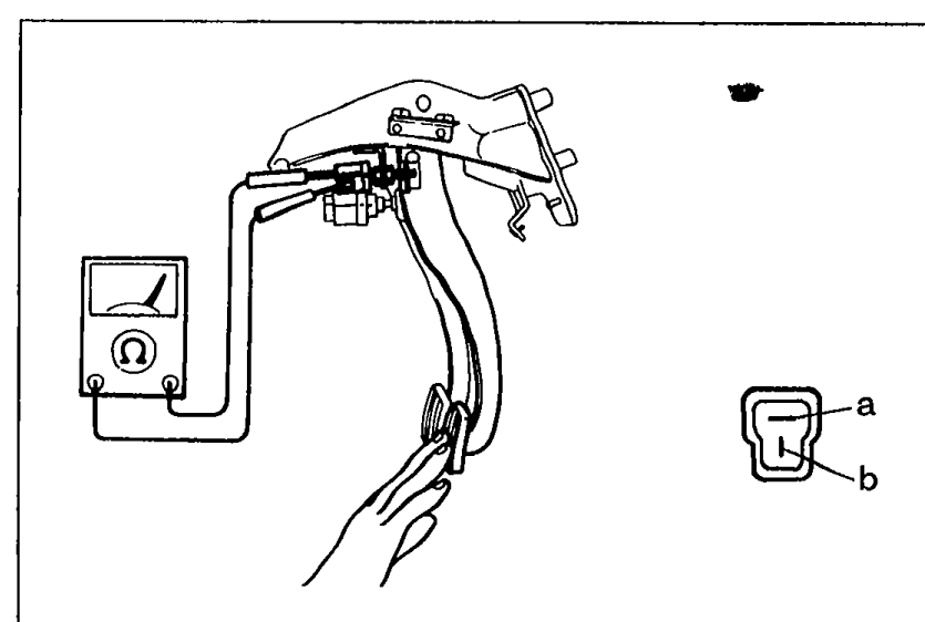
- 1Disconnect the stoplight switch.
 05U0TX-217
 - 2Check continuity between terminals of the switch.
- 3If not as specified, replace the stoplight switch.
- 4If the siwtch is OK, repair the wire harness. (Cruise control unit — Stoplight switch)
Stoplight switch continuity
Pedal released
a
b
Pedal depressed
aO——————O
b
NOTE
O——O: Indicates continuity
Step 8 — Inspection of actuator
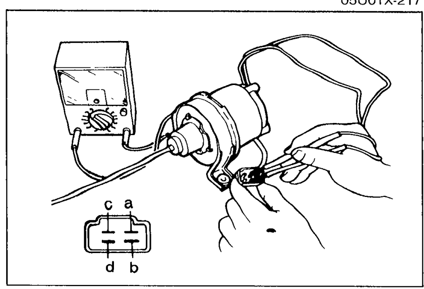
- 1Measure the actuator solenoid resistance using an ohmmeter.
 05U0TX-218
 - 2If not as specified, replace the actuator.
- 3If continuity is OK, go to Step 8—4.
- 4Disconnect the actuator cable from the accelerator pedal.
- 5Run the engine at idle speed.
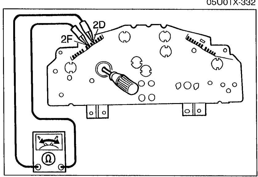
- 6Apply 12V to the following terminals, and check actuator operation.
 05U0TX-332
 - 7If not as specified, replace the actuator.
Actuator solenoid resistance
c — a
ResistanceApprox. 25 to 55Ω
c — b
ResistanceApprox. 25 to 55Ω
c — d
ResistanceApprox. 25 to 55Ω
Actuator 12V application test
1
aGround
bGround
cPower
dGround
Operation of control cablePull
2
aGround
b—
cPower
dGround
Operation of control cableHold
3
aGround
b—
cPower
d—
Operation of control cableExtend
4
a—
b—
c—
d—
Operation of control cableRelease
Step 9 — Inspection of speed sensor
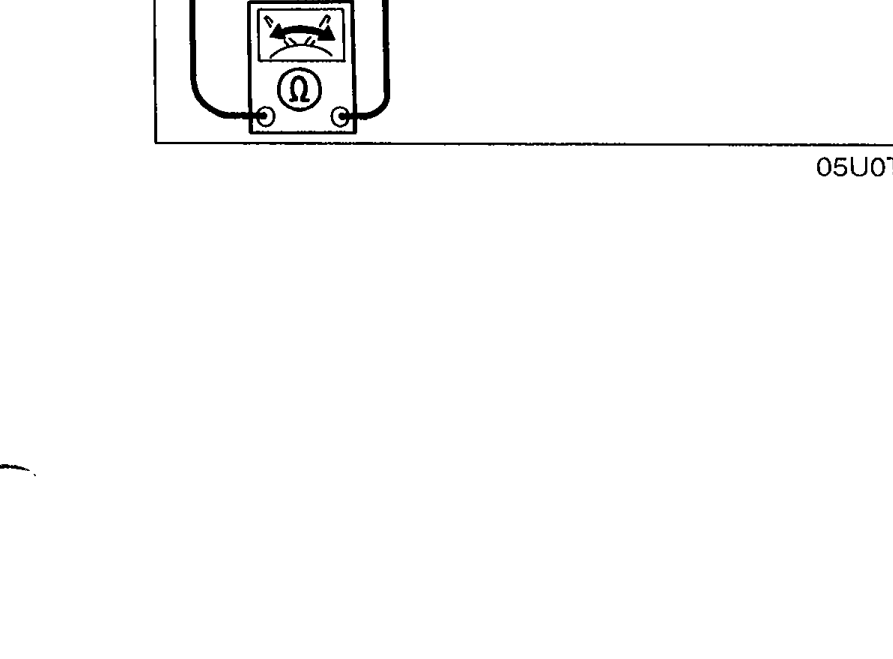
- 1Remove the instrument cluster.
 05U0TX-219
 - 2Check continuity between terminals 2D and 2F while rotating the speedometer cable.
- 3If there are not four pulses per shaft rotation, replace the speed sensor. (Refer to page T-33.)
- 4If there are four pulses per rotation, check the wire harness (Instrument cluster — Control unit).
- 5If the wiring is OK, replace the cruise control unit.