
CRUISE CONTROL SYSTEM
T-99prose procedureTROUBLESHOOTING
IMPORTANT
Symptom: Vehicle speed cannot be set. (Cruise control unit will not hold vehicle speed.)
NOTE
Before troubleshooting of the system, verify the following items:
1. Is system being correctly used by customer?
2. Is fuse OK?
Check the fuse. If the fuse is burned, replace it. Check the wire harness for a short circuit.
Step 1
- 1Turn the ignition switch ON.
 05U0TX-211
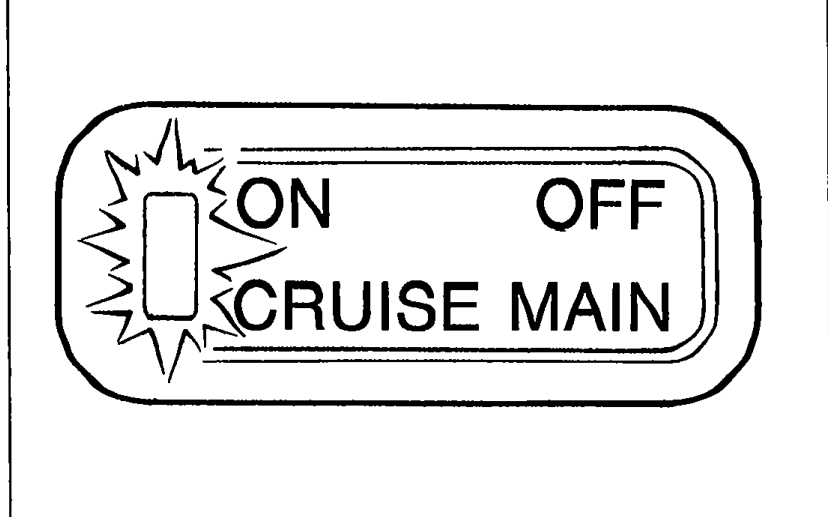
 - 2Turn the cruise control main switch ON.
- 3Check that the main switch indicator lamp comes ON.
- 4If the lamp does not come ON, go to Step 2.
- 5If the lamp comes ON, go to Step 3.
Step 2
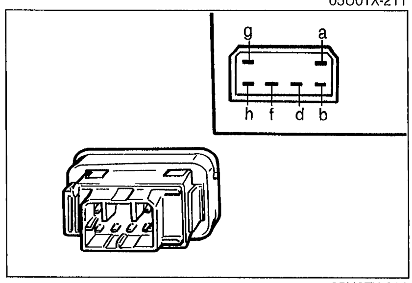
- 1Check continuity between terminals of the cruise control main switch.
 05U0TX-212
 - 2If not as specified, replace the switch.
- 3If the switch is OK, repair the wire harness. (METER 10A fuse — Cruise control main switch — Ground)
Step 2 — Cruise control main switch continuity
Neutral
a
b
dO—O
fO—O
gO—O
hO—O
Off
a
b
d
f
g
h
On
aO—O
bO—O
d
f
gO—O
hO—O
Step 3
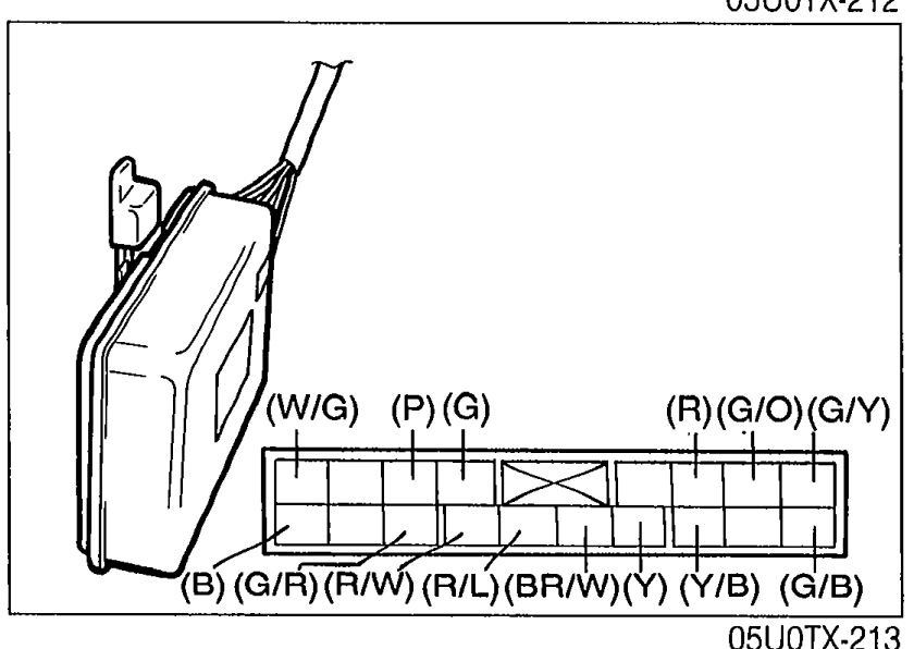
- 1Measure the voltage at the following terminal-wires of the cruise control unit connector.
 05U0TX-213
 - 2If all terminal voltage are OK, replace the cruise control unit.
Step 3 — Cruise control unit terminal voltages
a
Wire color(G/Y)
Connected toActuator
Test conditionMain switch off
Specification0V
ActionGo to Step 8
a
Wire color(G/Y)
Connected toActuator
Test conditionMain switch on
Specification9V
ActionGo to Step 8
b
Wire color(G/B)
Connected toActuator
Test conditionMain switch off
Specification0V
ActionGo to Step 8
b
Wire color(G/B)
Connected toActuator
Test conditionMain switch on
Specification9V
ActionGo to Step 8
c
Wire color(G/O)
Connected toActuator
Test conditionMain switch off
Specification0V
ActionGo to Step 8
c
Wire color(G/O)
Connected toActuator
Test conditionMain switch on
Specification9V
ActionGo to Step 8
e
Wire color(R)
Connected toMain switch
Test conditionMain switch off
Specification12V
ActionRepair wire (R) (Main switch—Cruise control unit)
e
Wire color(R)
Connected toMain switch
Test conditionMain switch off
Specification0V
ActionRepair wire (R) (Main switch—Cruise control unit)
f
Wire color(Y/B)
Connected toMain switch
Test conditionMain switch off
Specification0V
ActionRepair wire (Y/B) (Main switch—Cruise control unit)
f
Wire color(Y/B)
Connected toMain switch
Test conditionMain switch on
Specification12V
ActionRepair wire (Y/B) (Main switch—Cruise control unit)
See also
Step 8