
AIR BAG SYSTEM
T-145prose procedureStep 4
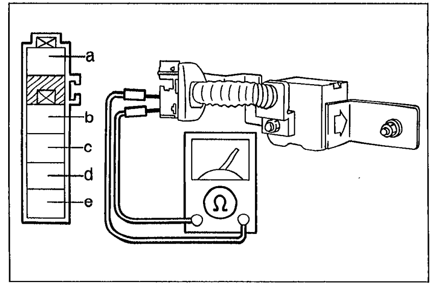
- 1Disconnect the S-sensor connectors.
 05U0TX-391
 - 2Check continuity between terminals of the sensor.
Step 4 — Continuity check (S-sensor terminals)
(b)—(e)
ContinuityYes
ActionReplace wire harness
(b)—(e)
ContinuityNo
ActionReplace S-sensor
Step 5
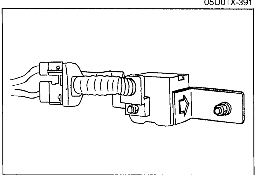
- 1Verify that the S-sensor is installed properly.
 05U0TX-392
 - 2If the installation is poor, clean the mounting and tighten the bolts.
- 3If correct, go to Step 6.
Step 6
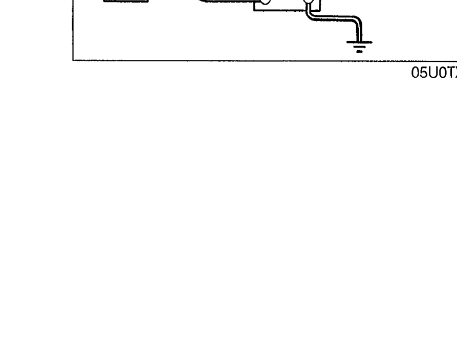
- 1Disconnect the S-sensor connectors.
 05U0TX-393
 - 2Check continuity between terminal of the sensor and a body ground.
Step 6 — Continuity check (S-sensor terminal to body ground)
(a)— Body ground
ContinuityYes
ActionReplace S-sensor
(a)— Body ground
ContinuityNo
ActionReplace wire harness