
LIGHTING SYSTEM — Inspection (Canada spec., Headlight relay, Retractor relay)
T-57prose procedureUnverifiedHeadlight relay inspection is U.S. spec.; headlight switch table shows Canada-spec terminals (HB, BTN).
Headlight switch — Canada spec.
Headlight switch (Canada spec.) inspection
- 1Remove the column cover and disconnect the headlight switch connectors.
- 2Check for continuity between terminals of the switch.
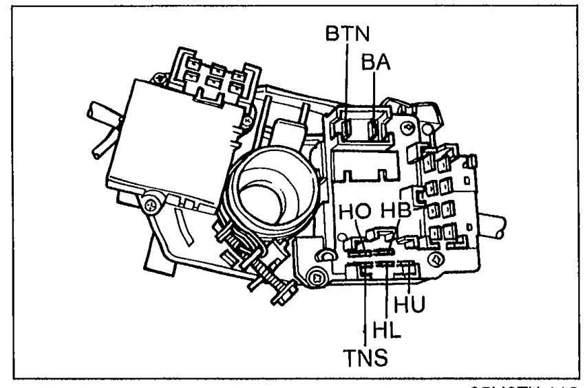 05U0TX-113
Headlight switch (Canada spec.) continuity
Headlight
Low beam
HB
HLO
HU
BAO
BTNO
TNS
Headlight
High beam
HBO
HL
HUO
BAO
BTNO
TNS
Passing
HB
HL
HUO
BA
BTNO
TNS
Tail, Parking
HB
HL
HU
BAO
BTNO
TNSO
NOTE
O—O: Indicates continuity
Headlight relay (U.S. spec.)
Headlight relay (U.S. spec.) inspection
- 1Check continuity between terminals 3 and 4.
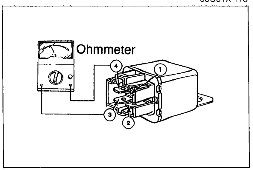 05U0TX-114
 - 2If not as specified, replace the headlight relay.
- 3If correct, go to Step 4.
- 4Apply 12V to terminal 1 and ground terminal 2. Check for continuity between terminals 3 and 4.
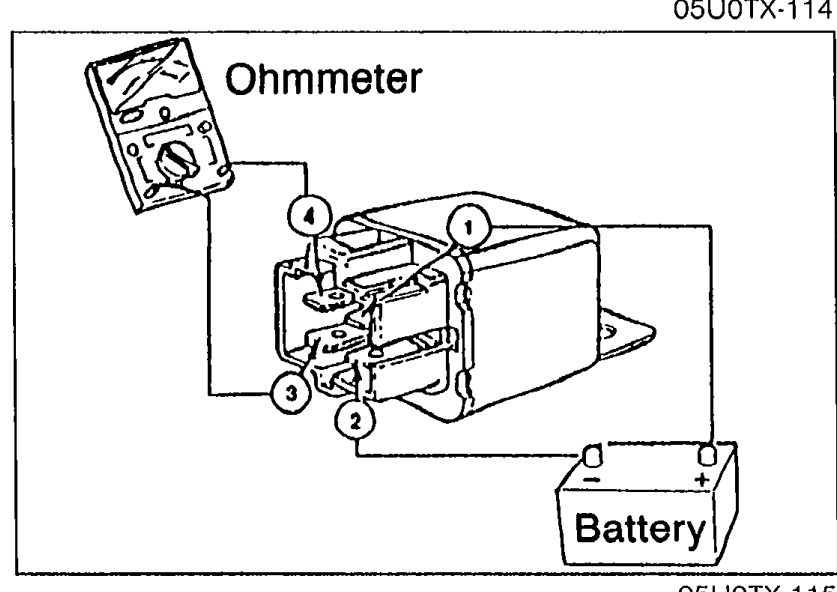 05U0TX-115
 - 5If not as specified, replace the headlight relay.
Headlight relay — Step 1 continuity (de-energized)
3—4
ContinuityNo
Headlight relay — Step 4 continuity (energized)
3—4
ContinuityYes
Headlight retractor relay
Headlight retractor relay inspection
- 1Check continuity between terminals of the relay.
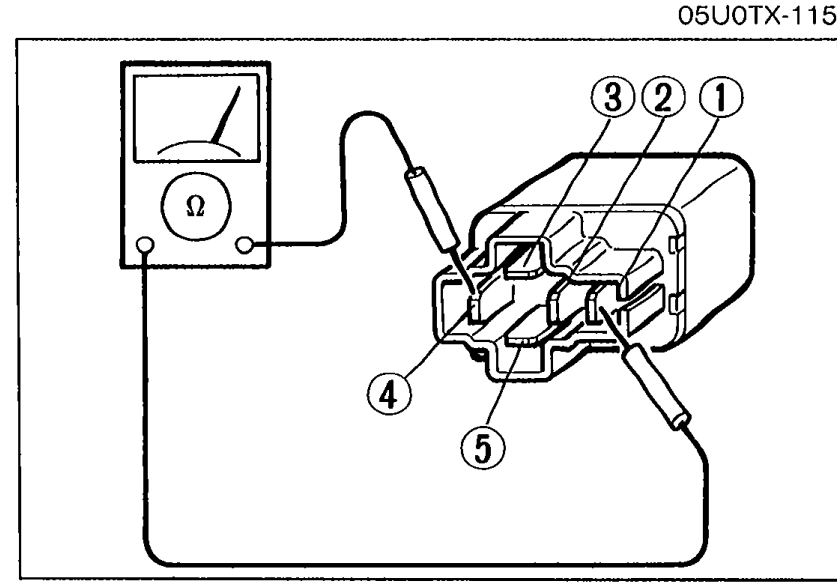 05U0TX-116
 - 2If not as specified, replace the retractor relay.
- 3If correct, go to Step 4.
- 4Apply 12V to terminal 3 and ground terminal 5. Check continuity between terminals of the relay.
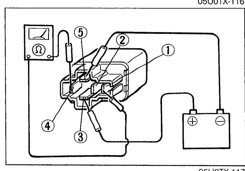 05U0TX-117
 - 5If not as specified, replace the retractor relay.
Retractor relay — Step 1 continuity (de-energized)
1—4
ContinuityYes
2—4
ContinuityNo
3—5
ContinuityYes
Retractor relay — Step 4 continuity (energized)
1—4
ContinuityNo
2—4
ContinuityYes