
CRUISE CONTROL SYSTEM — CRUISE CONTROL UNIT
T-105prose procedureClutch switch terminal (j) applies to M/T models only.
CRUISE CONTROL UNIT
Removal
Cruise control unit removal
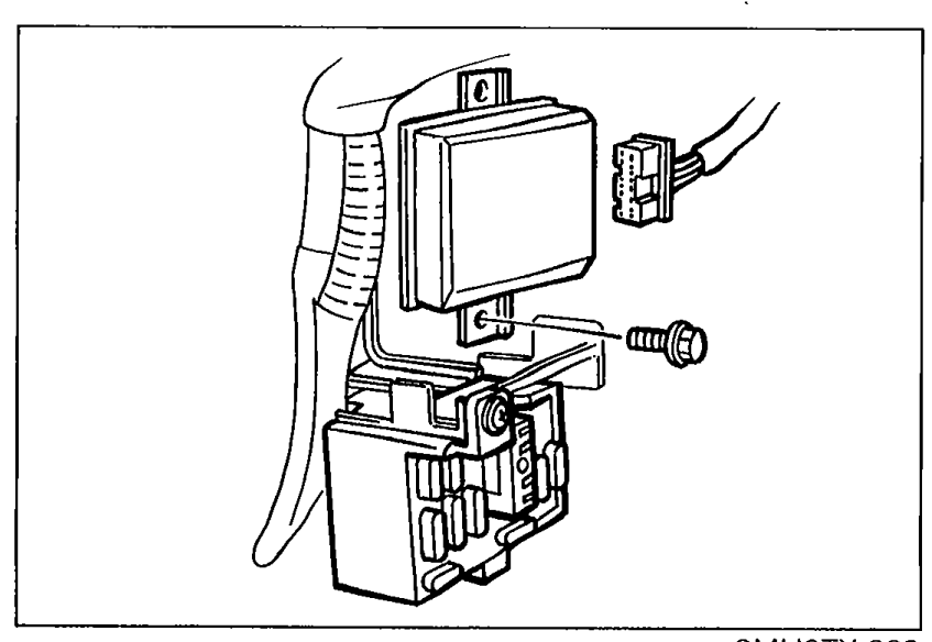
- 1Remove the passenger side kick panel.
 9MU0TX-268
 - 2Remove the nut and the control unit.
Installation
NOTE
Install in the reverse order of removal.
Inspection
Cruise control unit inspection
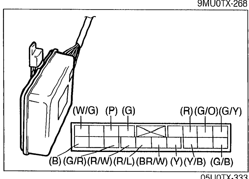
- 1Check the terminal voltages of the control unit.
 05U0TX-333
 - 2If the terminal voltages are correct, replace the control unit.
Cruise control unit terminal voltages
a
Wire colorG/Y
Connected toActuator
Test conditionMain switch OFF
Specification0V
ActionCheck actuator (Refer to page T-104)
a
Wire colorG/Y
Connected toActuator
Test conditionMain switch ON
Specification9V
ActionCheck actuator (Refer to page T-104)
b
Wire colorG/B
Connected toActuator
Test conditionMain switch OFF
Specification0V
ActionCheck actuator (Refer to page T-104)
b
Wire colorG/B
Connected toActuator
Test conditionMain switch ON
Specification9V
ActionCheck actuator (Refer to page T-104)
c
Wire colorG/O
Connected toActuator
Test conditionMain switch OFF
Specification0V
ActionCheck actuator (Refer to page T-104)
c
Wire colorG/O
Connected toActuator
Test conditionMain switch ON
Specification9V
ActionCheck actuator (Refer to page T-104)
e
Wire colorR
Connected toMain switch
Test conditionMain switch OFF
Specification12V
ActionCheck main switch (Refer to page T-107)
e
Wire colorR
Connected toMain switch
Test conditionMain switch ON
Specification0V
ActionCheck main switch (Refer to page T-107)
f
Wire colorY/B
Connected toMain switch
Test conditionMain switch OFF
Specification0V
ActionCheck main switch (Refer to page T-107)
f
Wire colorY/B
Connected toMain switch
Test conditionMain switch ON
Specification12V
ActionCheck main switch (Refer to page T-107)
h
Wire colorY
Connected toBrake switch
Test conditionBrake pedal depressed
Specification0V
ActionCheck brake switch (Refer to page T-107)
h
Wire colorY
Connected toBrake switch
Test conditionBrake pedal released
Specification9V
ActionCheck brake switch (Refer to page T-107)
j
Wire colorBR/W
Connected toClutch switch
Test conditionClutch pedal depressed
Specification0V
ActionCheck clutch switch (Refer to page T-107)
j
Wire colorBR/W
Connected toClutch switch
Test conditionClutch pedal released
Specification12V
ActionCheck clutch switch (Refer to page T-107)
l
Wire colorR/L
Connected toCruise control switch (Set switch and Coast switch)
Test conditionMain switch ON
Specification12V
ActionCheck cruise control switch (Refer to page T-107)
l
Wire colorR/L
Connected toCruise control switch (Set switch and Coast switch)
Test conditionWhile pushing set switch Main switch ON
Specification0V
ActionCheck cruise control switch (Refer to page T-107)
m
Wire colorG
Connected toStoplight switch
Test conditionBrake pedal depressed
Specification12V
ActionCheck stoplight switch (Refer to page T-61)
m
Wire colorG
Connected toStoplight switch
Test conditionBrake pedal released
Specification0V
ActionCheck stoplight switch (Refer to page T-61)
n
Wire colorR/W
Connected toCruise control switch (Resume switch and Accel switch)
Test conditionMain switch ON
Specification12V
ActionCheck cruise control switch (Refer to page T-107)
n
Wire colorR/W
Connected toCruise control switch (Resume switch and Accel switch)
Test conditionWhile pushing resume switch Main switch ON
Specification0V
ActionCheck cruise control switch (Refer to page T-107)
o
Wire colorP
Connected toActuator
Test conditionMain switch OFF
Specification0V
ActionCheck actuator (Refer to page T-104)
o
Wire colorP
Connected toActuator
Test conditionMain switch ON
Specification9V
ActionCheck actuator (Refer to page T-104)
p
Wire colorG/R
Connected toSpeed sensor
Test conditionWhile rotating rear tires
SpecificationCycles 0—5V
ActionCheck speed sensor (Refer to page T-107)
s
Wire colorW/G
Connected toBattery
Test conditionConstant
Specification12V
ActionRepair wire