Mazda MX-5 NA silhouetteMX-5 NA

AIR BAG SYSTEM

T-147prose procedure

Step 5

  1. 1
    Check continuity between terminal-wire 2F (G/Y) of the diagnostic module connector and a body ground.
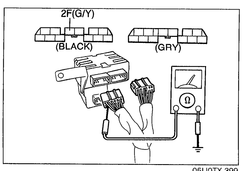
    Diagnostic module connector diagram showing two connector blocks labelled (BLACK) and (GRY), with terminal 2F (G/Y) called out at the top. An ohmmeter is shown with one probe on terminal 2F (G/Y) and the other probe on a body ground, for the Step 5 continuity check.
    05U0TX-399
  2. 2
    If not as specified, replace the wire harness assembly.
  3. 3
    If correct, replace the air bag module.

Step 5 — Terminal-wire to body ground continuity

2F (G/Y)—Body ground
ContinuityNo

Search Manual

Search pages, specs, and procedures