
AIR BAG SYSTEM
T-146prose procedureFlowchart No. 6
Fault indication
DescriptionWarning lamp flashes six times
Possible cause
DescriptionFaulty air bag module or poor connection of clock spring connector
CAUTION
Before troubleshooting, read SERVICE PRECAUTION on page T-133.
Step 1
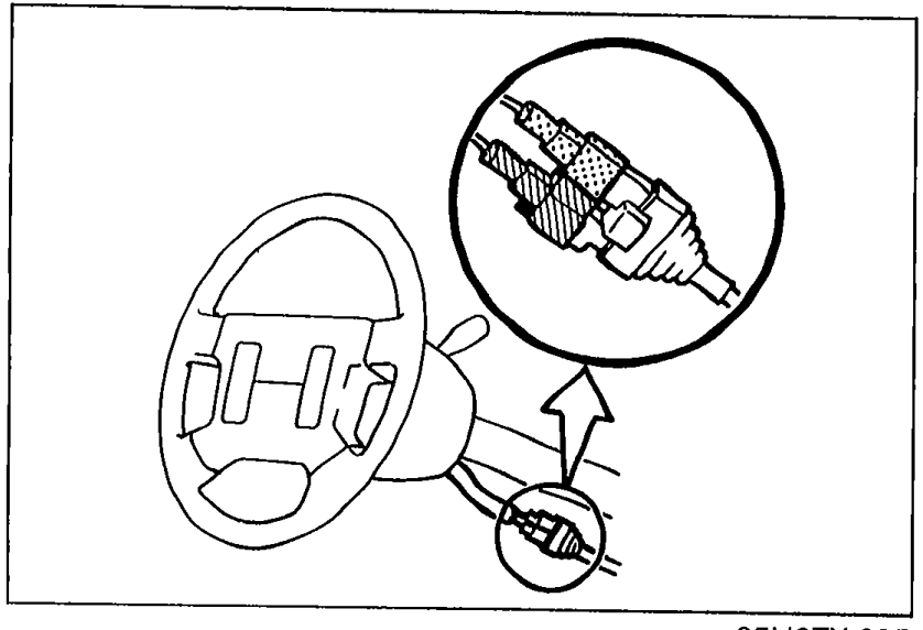
- 1Disconnect the negative battery cable.
 05U0TX-395
 - 2Check for proper connection of the clock spring connectors (Orange and blue).
- 3If a connector is loose or disconnected, reconnect it.
- 4If the connections are OK, go to Step 2.
Step 2
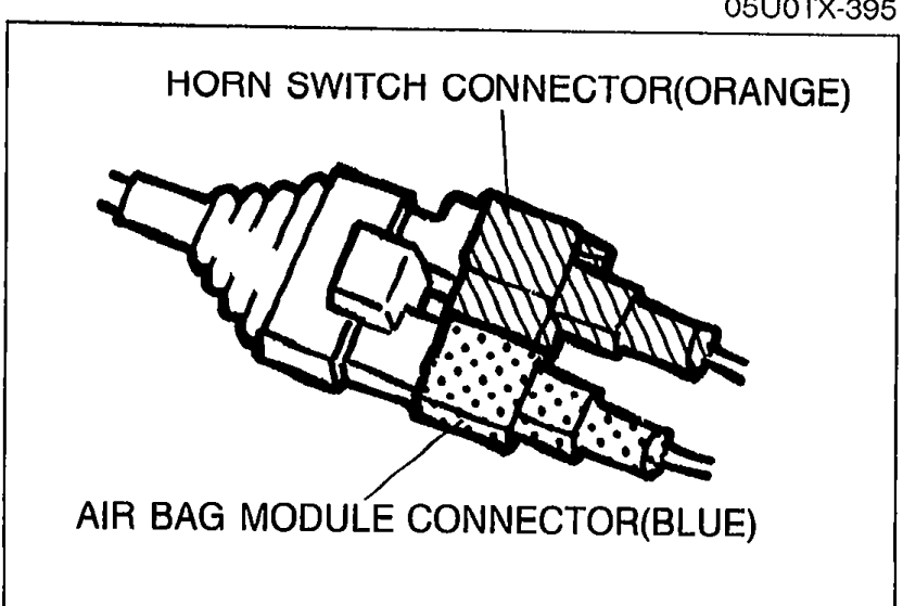
- 1Remove the air bag module installation nuts.
 05U0TX-396
 - 2Verify that the air bag module connector is properly connected.
- 3If the connector is loose or disconnected, reconnect it.
- 4If the connection is OK, go to Step 3.
Step 3
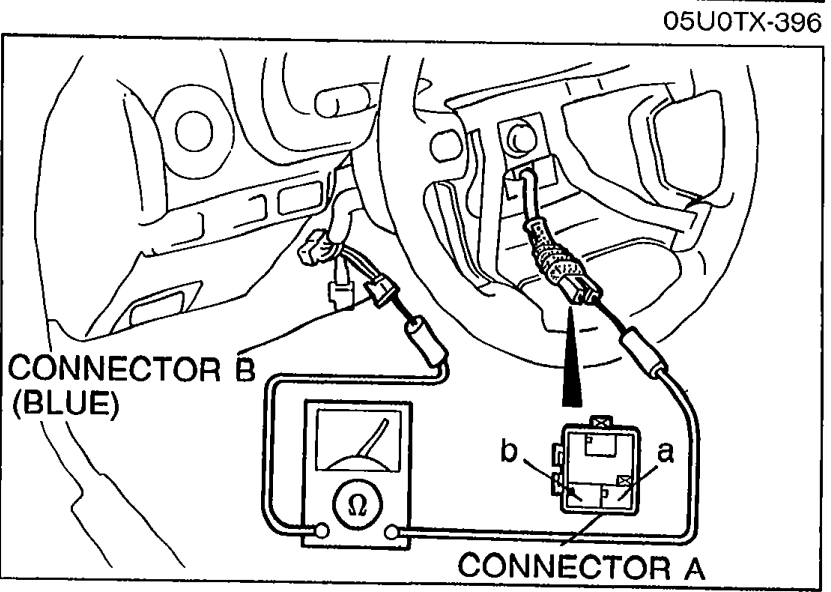
- 1Disconnect the air bag module and clock spring connector.
 05U0TX-397
 - 2Check continuity between terminals of the clock spring connectors (blue) as shown.
- 3If not as specified, replace the clock spring connector.
Step 3 — Clock spring (blue) continuity
a
Connector BA
ContinuityYes
b
Connector BB
ContinuityYes
Step 4
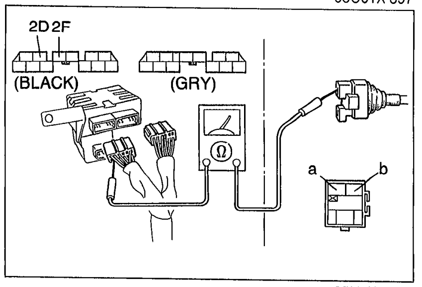
- 1Disconnect the diagnostic module connector.
 05U0TX-398
 - 2Check continuity between the diagnostic module connector and the clock spring connector (wire harness side) as shown.
- 3If not as specified, replace the wire harness assembly.
- 4If correct, go to Step 5.
Step 4 — Diagnostic module to clock spring continuity
(2D) : G/W
Clock spring connector(a : R)
ContinuityYes
(2F) : G/Y
Clock spring connector(b : G/Y)
ContinuityYes