
HORN — TROUBLESHOOTING (continued)
T-94prose procedureCanada spec. variant of Step 4 — air bag not present, simpler continuity check on steering shaft serration gear.
Canada spec.
Step 4 — Canada spec.
- 1Remove the steering shaft.
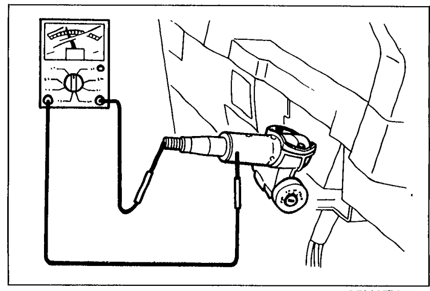 05U0TX-196
 - 2Check continuity between the horn conductor plate and the serration gear part.
- 3If not as specified, replace the horn switch and steering wheel as an assembly.
- 4If correct, repair wire (G/O) (Horn relay — horn switch).
Horn switch continuity
ON
ContinuityYes
OFF
ContinuityNo
Step 5
- 1Remove the knee protector.
- 2Disconnect the clock spring connector.
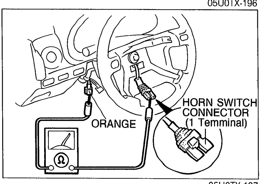 05U0TX-197
 - 3Check continuity of the clock spring connector as shown in the figure.
Clock spring continuity remedy
Yes
ActionRepair wire (G/O) (Horn relay — Clock spring connector)
No
ActionReplace combination switch assembly
WARNING
After installation of the air bag module, verify that the air bag system is operating normally by monitoring the air bag warning lamp. (Refer to page T-138.)
Step 6
- 1Ground the terminal wire (G/O) of the horn relay connector.
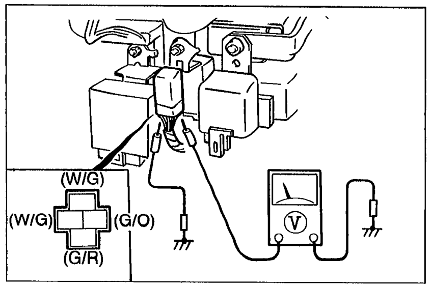 05U0TX-198
 - 2Measure the voltage at the following terminal wires of the horn relay connector.
Horn relay connector voltage check
(G/W) Terminal A
Voltage12V
ActionNext check wire (G/W) of terminal D
(G/W) Terminal A
Voltage0V
ActionRepair wire (G/W) (STOP 15A fuse — Horn relay)
(G/W) Terminal D
Voltage12V
ActionNext check wire (G/R)
(G/W) Terminal D
Voltage0V
ActionRepair wire (G/W) (STOP 15A fuse — Horn relay)
(G/R)
Voltage12V
ActionRepair wire (G/R) (Horn relay — Horn)
(G/R)
Voltage0V
ActionReplace horn relay