
INSTRUMENT CLUSTER
T-36prose procedureOil Pressure Gauge Inspection (continued)
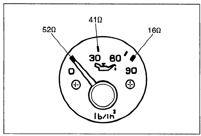
- 4Set the SST to the resistance values shown in the figure.
 9MU0TX-087
 - 5Verify that the needle indicates the correct values.
CAUTION
Continue the above checks for at least two minutes each to correctly judge the condition.
The allowable indication error is twice the width of the needle.
Printed Circuit Inspection
- 1Remove the instrument cluster. (Refer to page T-33.)
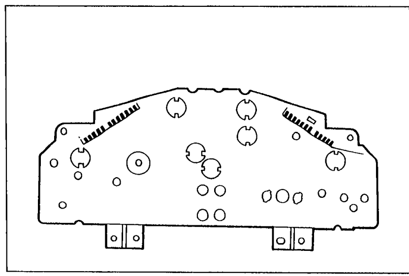
- 2Check the printed circuit for damage or oxidization.
 05U0TX-067
 - 3If necessary, replace the printed circuit.
Speed Sensor Inspection
- 1Remove the instrument cluster.
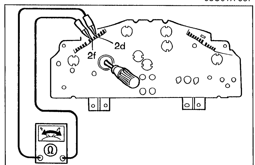
- 2Check continuity between terminals 2d and 2f while rotating the speedometer cable shaft.
 05U0TX-297
 - 3If the correct number of pulsations fail to occur during each shaft rotation, replace the speed sensor. (Refer to page T-33.)
| Specification | Value |
|---|---|
| Pulsation | 4/shaft rotation |
Pulsation
4/shaft rotation
Water Thermosensor Inspection
- 1Remove the sensor.
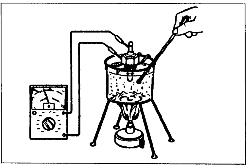
- 2Place the sensor and a thermometer in water.
 05U0TX-069
 - 3Heat the water gradually, and measure the resistance of the sensor with an ohmmeter.
- 4If the resistance is not as specified, replace the sensor.
| Specification | Value |
|---|---|
| Resistanceat 50°C (122°F) | 190 — 260 ohm |
Resistanceat 50°C (122°F)
190 — 260 ohm
FUEL GAUGE SENDER UNIT (IN FUEL TANK) Inspection
Fuel Gauge Sender Unit Inspection
- 1Remove the fuel tank gauge sender unit. (Refer to Section F.)
- 2Disconnect the fuel gauge sender unit connector.
- 3Check resistance between terminals a and b while slowly moving the unit arm from point F to point E.
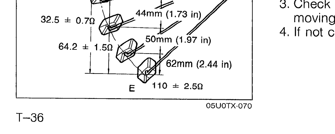 05U0TX-070
 - 4If not correct, replace the fuel gauge sender unit.
Fuel Gauge Sender Resistance vs Travel
F
Resistance (ohm)3 ± 0.6
Travel—
Resistance (ohm)15.8 ± 0.6
Travel45 mm (1.77 in)
Resistance (ohm)32.5 ± 0.7
Travel44 mm (1.73 in)
Resistance (ohm)64.2 ± 1.5
Travel50 mm (1.97 in)
E
Resistance (ohm)110 ± 2.5
Travel62 mm (2.44 in)