
LIGHTING SYSTEM — Troubleshooting: Turn and hazard warning lights do not operate (U.S. spec.)
T-63prose procedureUnverifiedU.S. specification only.
Troubleshooting
Symptom: Turn and hazard warning lights do not operate (U.S. spec.)
Turn and hazard warning lights do not operate (U.S. spec.)
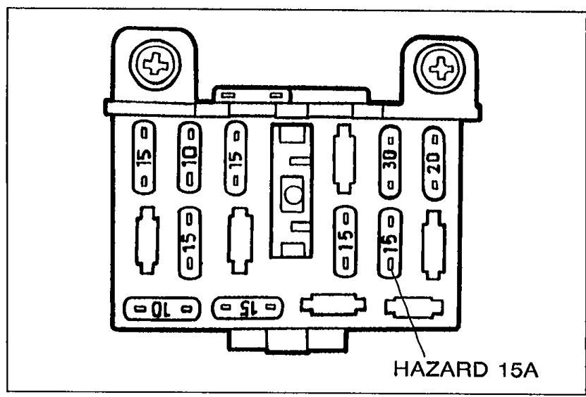
- 1Check HAZARD 15A fuse in the fuse box.
 05U0TX-301
 - 2If the fuse is burned replace it. Check and repair the wire harness, if necessary.
- 3If the fuse is OK, go to Step 2.
Step 2 — Check turn and hazard warning flasher unit
Check turn and hazard warning flasher unit
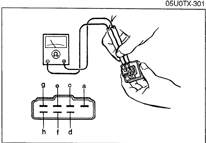
- 1Remove the turn and hazard warning flasher unit.
 05U0TX-302
 - 2Check continuity between terminals of the unit with an ohmmeter.Set the ohmmeter to ×1000Ω range.
- 3If not as specified, replace the flasher unit.
- 4If the flasher unit is OK, reconnect the connector and go to Step 3.
Turn and hazard warning flasher unit terminal continuity
a — c
ContinuityX
a — d
ContinuityX
a — e
ContinuityO
a — f
ContinuityO
a — g
ContinuityX
a — h
ContinuityX
c — a
ContinuityO
c — d
ContinuityO
c — e
ContinuityO
c — f
ContinuityX
c — g
ContinuityO
c — h
ContinuityO
d — a
ContinuityX
d — c
ContinuityX
d — e
ContinuityX
d — f
ContinuityX
d — g
ContinuityO
d — h
ContinuityO
e — a
ContinuityO
e — c
ContinuityX
e — d
ContinuityX
e — f
ContinuityX
e — g
ContinuityX
e — h
ContinuityX
f — a
ContinuityX
f — c
ContinuityX
f — d
ContinuityX
f — e
ContinuityX
f — g
ContinuityX
f — h
ContinuityX
g — a
ContinuityX
g — c
ContinuityX
g — d
ContinuityX
g — e
ContinuityO
g — f
ContinuityX
g — h
ContinuityX
h — a
ContinuityO
h — c
ContinuityX
h — d
ContinuityX
h — e
ContinuityX
h — f
ContinuityX
h — g
ContinuityX
NOTE
O: Indicates continuity X: No continuity
Step 3
Check turn signal switch
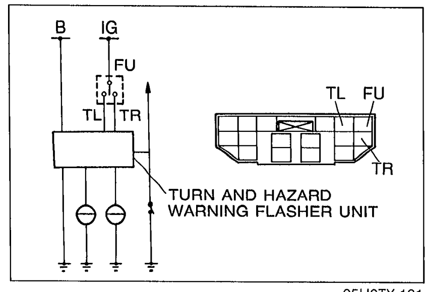
- 1Remove the knee protector, then disconnect the turn signal switch connector.
 05U0TX-131
 - 2Check continuity between terminals of the switch.
- 3If not as specified, replace the turn signal switch.
- 4If the turn signal switch is OK, reconnect the connector and go to Step 4.
Turn signal switch continuity
Left
FUO
TLO
TR
Right
FUO
TL
TRO
NOTE
O—O: Indicates continuity