
INSTRUMENT CLUSTER
T-31prose procedureIMPORTANT
Symptom: Fuel gauge does not operate.
Preparation SST
| Specification | Value |
|---|---|
| SSTFor inspection of gauges | 49 0839 285 Checker, fuel and thermometer |
SSTFor inspection of gauges
49 0839 285 Checker, fuel and thermometer
Step 1
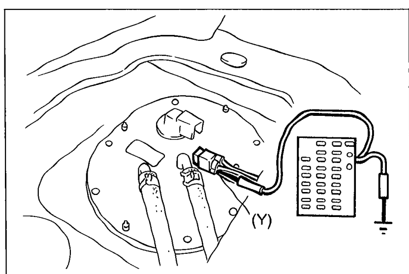
- 1Disconnect the connector from the fuel tank sender unit.
 05U0TX-283
 - 2Connect the red lead of the SST to terminal-wire (Y) and the black lead to a body ground.
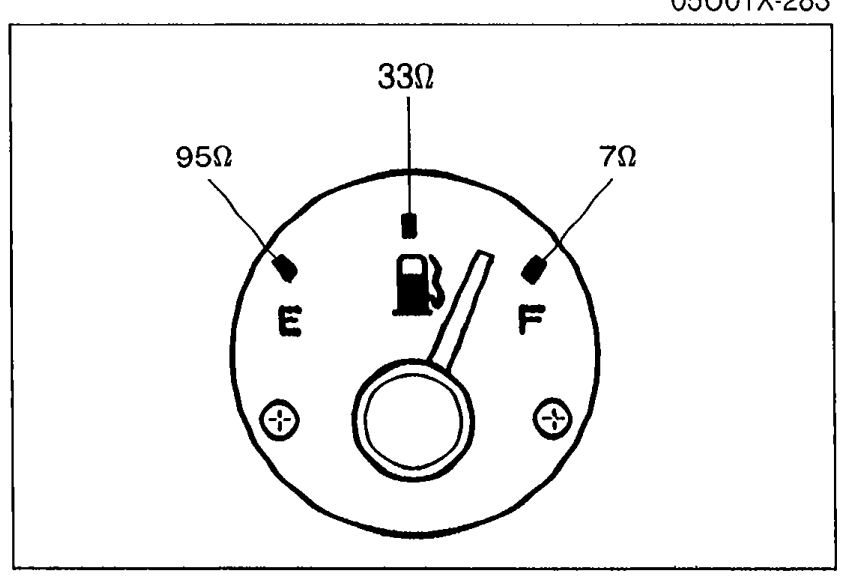
- 3Set the SST to the resistance values shown in the figure.
 9MU0TX-079
 - 4Turn the ignition switch ON, and verify that the needle indicates the correct values.
Step 1 Diagnostic Result
Yes
ActionReplace fuel gauge sender unit (in fuel tank)
No
ActionGo to Step 2
CAUTION
Continue the above checks for at least two minutes each to correctly judge the condition.
The allowable indication error is twice the width of the needle.
Step 2
- 1Remove the instrument cluster. (Refer to page T-33.)
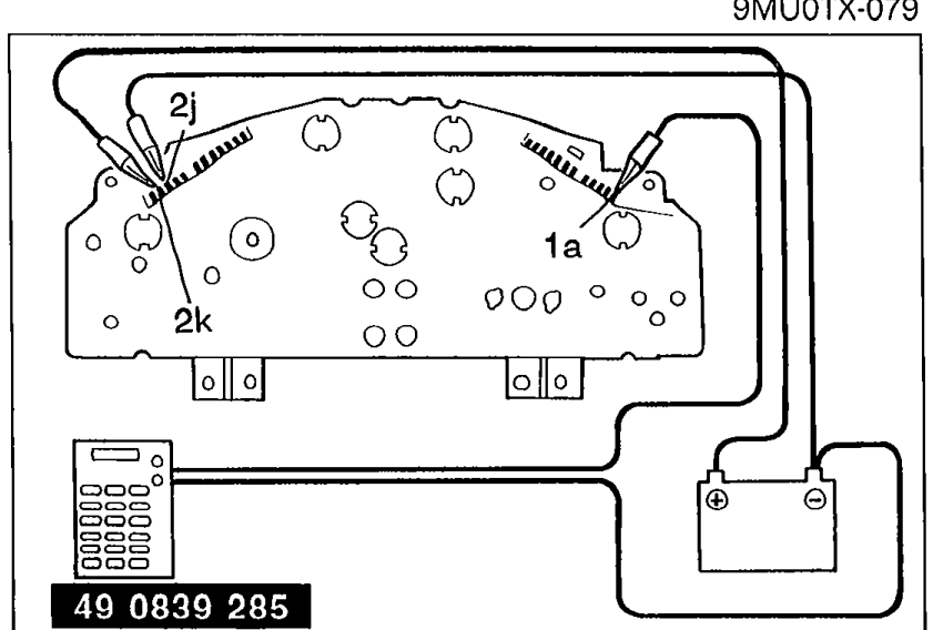
- 2Apply 12V to terminal 2k and ground terminal 2j.
 05U0TX-284
 - 3Connect the red lead of the SST to terminal 1a and the black lead to a ground.
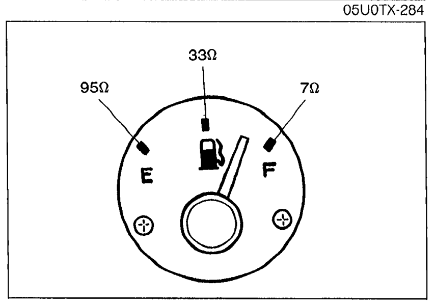
- 4Set the SST to the resistance values shown in the figure.
 05U0TX-285
 - 5Verify that the needle indicates the correct values.
Step 2 Diagnostic Result
Yes
ActionRepair wiring harness (Instrument cluster — fuel gauge sender unit)
No
ActionReplace fuel gauge
CAUTION
Continue the above checks for at least two minutes each to correctly judge the condition.
The allowable indication error is twice the width of the needle.