
AUDIO — Inspection (Door Speakers, Headrest Speakers) and Connector Terminal Specifications
T-128prose procedureUnverifiedINSPECTION
Door Speakers
Door Speakers Inspection
- 1Disconnect the connector from the suspected faulty speaker.
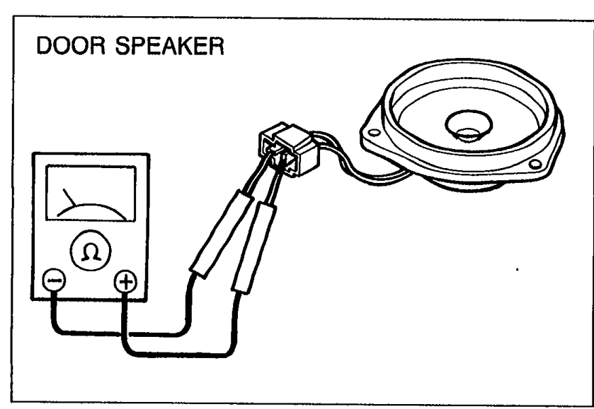 05U0TX-270
 - 2Measure resistance between terminals of the speaker. Resistance: 4Ω
- 3If not as specified, replace the speaker.
| Specification | Value |
|---|---|
| Door speaker resistancebetween terminals | 4Ω |
Door speaker resistancebetween terminals
4Ω
Headrest Speakers
Headrest Speakers Inspection
- 1Disconnect the headrest speaker connector.
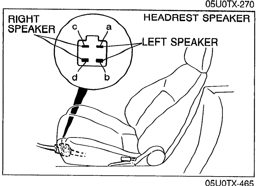 05U0TX-465
 - 2Measure resistance between terminals of the headrest speaker connector as shown.
- 3If not as specified, replace the speaker.
Headrest speaker resistance
a—b
Resistance
c—d
Resistance4Ω
CONNECTOR TERMINAL SPECIFICATIONS
Audio unit and Compact disc player connector terminals
Audio unit
ConnectorConnector with cells i,h,f,d,b (top) / j,e,c,a (bottom) — 6-pin
Terminala : Headrest speaker left (+)
b : Headrest speaker left (−)
c : NC
d : NC
f : Headrest speaker right (+)
h : Headrest speaker right (−)
i : NC
j : NC
Audio unit
ConnectorConnector with cells m,k,h,e,c,a (top) / n,l,j,f,d,b (bottom) — 14-pin
Terminala : ACC
b : NC
c : +B
d : NC
e : TNS (for illumination lamps)
f : NC
h : NC
j : NC
k : Door speaker left (+)
l : Door speaker left (−)
m : Door speaker right (+)
n : Door speaker right (−)
Audio unit
Connector13-pin round connector
Terminal1 : Left signal
2 : Left signal
3 : Right signal
4 : Right signal
5 : Signal ground
6 : Illumination signal
7 : ACC
8 : +B
9 : Amp control signal
10 : NC
11 : NC
12 : NC
13 : NC
Compact disc player
Connector13-pin round connector
Terminal1 : Left signal
2 : Left signal
3 : Right signal
4 : Right signal
5 : Signal ground
6 : Illumination signal
7 : ACC
8 : +B
9 : Amp control signal
10 : NC
11 : NC
12 : NC
13 : NC