
CRUISE CONTROL SYSTEM — Condition/operation code numbers / ACTUATOR
T-104prose procedureCondition/operation code numbers
NOTE
The test light will flash if a malfunction is present.
Cruise control diagnostic codes
1 short flash per cycle
Code No.01
Possible CauseDefective wiring or ground / Defective actuator / Defective brake switch
ActionRepair harness / Inspect actuator (See below)
5 short flashes per cycle
Code No.05
Possible CauseSTOP 15A fuse blown
ActionReplace fuse
7 short flashes per cycle
Code No.07
Possible CauseBoth stoplight switch and brake switch (for vehicle and cruise) are ON simultaneously
ActionInspect stoplight switch and brake switch (Refer to pages T-61 and T-107)
1 long flash + 1 short flash per cycle
Code No.11
Possible CauseDefective cruise control switch
ActionInspect cruise control switch (Refer to page T-107)
1 long flash + 5 short flashes per cycle
Code No.15
Possible CauseDefective cruise control unit
ActionGo to troubleshooting (Refer to page T-99)
NOTE
• If there is more than one malfunction, the code numbers will be indicated in numerical order lowest number first.
ACTUATOR
Inspection
Actuator inspection
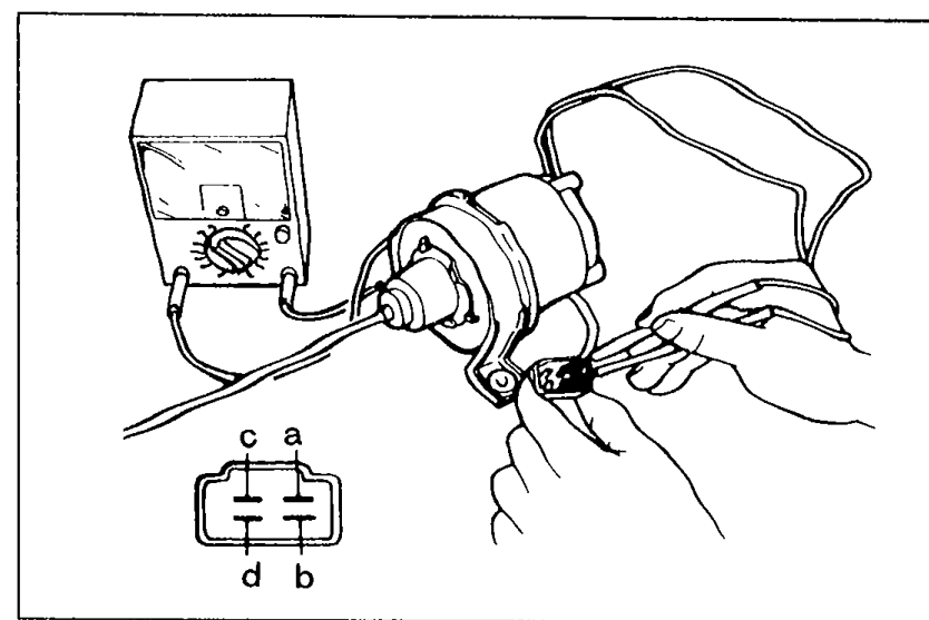
- 1Measure the actuator solenoid resistance using an ohmmeter.
 05U0TX-227
 - 2If not as specified, replace the actuator.
- 3Disconnect the actuator cable from the accelerator pedal.
- 4Run the engine at idle speed.
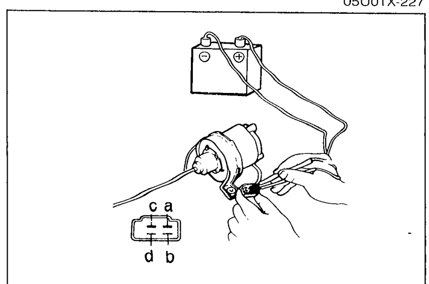
- 5Apply battery voltage to the following terminals, and check the actuator operation.
 05U0TX-459
 - 6If not as specified, replace the actuator.
Actuator solenoid resistance
c — a
ResistanceApprox. 25 to 55Ω
c — b
ResistanceApprox. 25 to 55Ω
c — d
ResistanceApprox. 25 to 55Ω
Actuator battery voltage operation test
1
aGround
bGround
cPower
dGround
Operation of control cablePull
2
aGround
b—
cPower
dGround
Operation of control cableHold
3
aGround
b—
cPower
d—
Operation of control cableExtend
4
a—
b—
c—
d—
Operation of control cableRelease
Removal
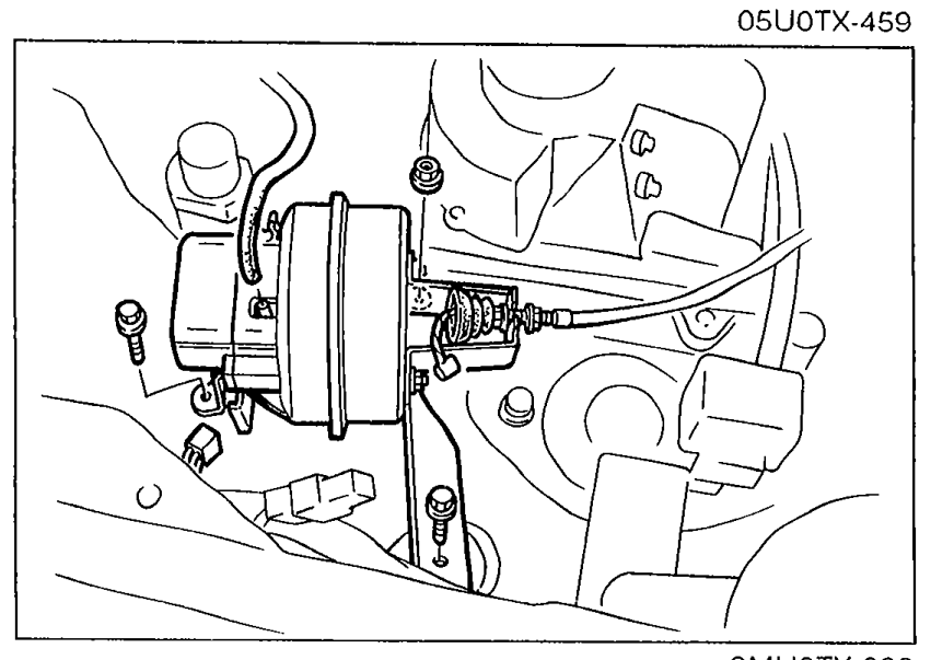
Actuator removal
- 1Disconnect the accelerator cable and vacuum hose from the actuator.
 9MU0TX-262
 - 2Remove the bolt and nuts and the actuator.
Installation
NOTE
Install in the reverse order of removal.