
CRUISE CONTROL SYSTEM
T-107prose procedureBRAKE SWITCH
Removal
Loosen the locknut and remove the switch.
Installation
Install in the reverse order of removal.
Adjustment
Adjust the switch to set the specified pedal height.
| Specification | Value |
|---|---|
| Pedal height | 171—181mm (6.93—7.13 in) |
| Pedal free play | 4—7mm (0.16—0.28 in) |
Pedal height
171—181mm (6.93—7.13 in)
Pedal free play
4—7mm (0.16—0.28 in)
Inspection
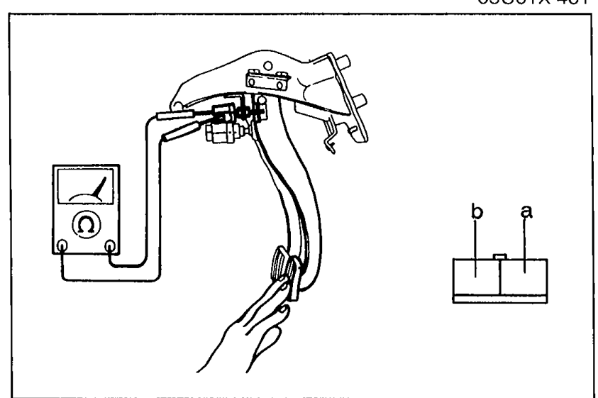
Brake Switch Inspection
- 1Disconnect the brake switch connector.
 05U0TX-230
 - 2Check continuity between terminals of the switch.
- 3If not as specified, replace the brake switch.
- 4If the switch is OK, repair the wire harness (Fuse — Brake switch — Control unit).
Brake switch continuity
Pedal released
Terminal aO
Terminal bO
Pedal depressed
Terminal a
Terminal b
NOTE
O—O: Indicates continuity
CRUISE CONTROL MAIN SWITCH
Inspection
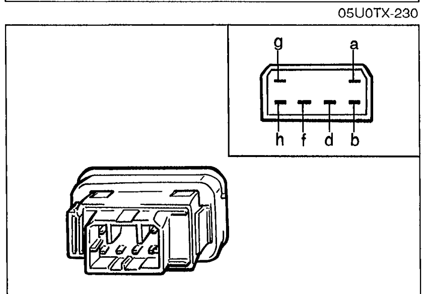
Cruise Control Main Switch Inspection
- 1Check continuity between terminals of the cruise control main switch.
 05U0TX-231
 - 2If not as specified, replace the cruise control main switch.
Cruise control main switch continuity
Neutral
a
b
d
f
g
h
Off
a
b
dO
fO
g
h
On
aO
bO
d
f
gO
hO
NOTE
O—O: Indicates continuity
CRUISE CONTROL SWITCH
Inspection
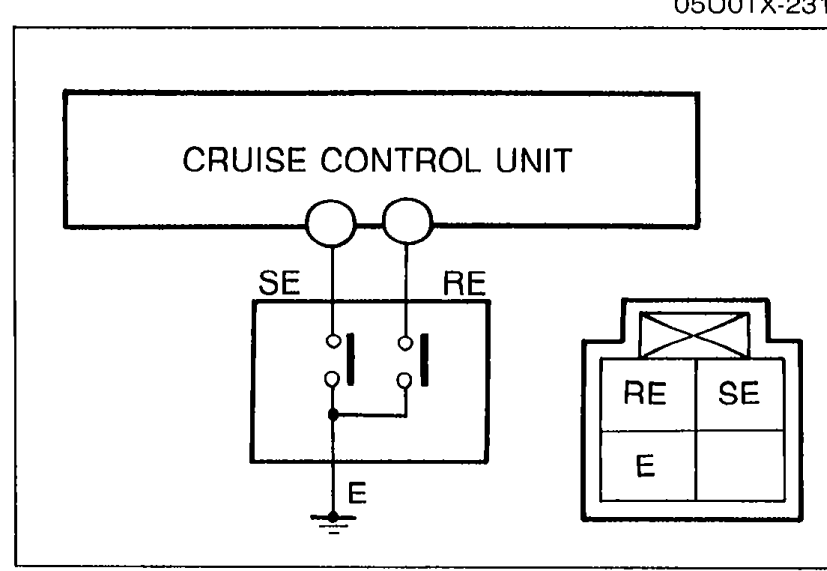
Cruise Control Switch Inspection
- 1Remove the knee protector and disconnect the combination switch connector.
 05U0TX-232
 - 2Check continuity between terminals of the combination switch connector.
- 3If not as specified, replace the cruise control switch.
Cruise control switch continuity
SET/COAST
SEO
RE
EO
RESUME/ACCEL
SE
REO
EO
NOTE
O—O: Indicates continuity
SPEED SENSOR
Inspection
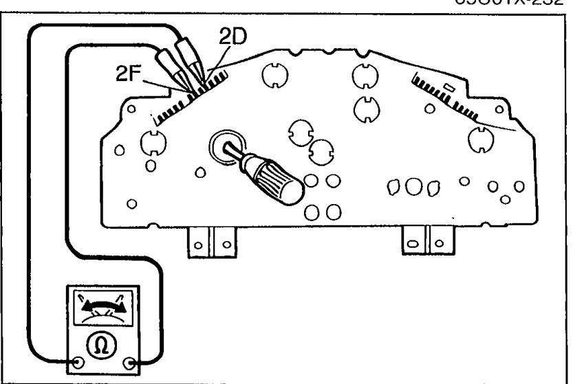
Speed Sensor Inspection
- 1Remove the instrument cluster.
 05U0TX-233
 - 2Check continuity between terminals 1L and 2A while rotating the speedometer cable.
- 3If there are not four pulses per shaft rotation, replace the speed sensor. (Refer to page T-33.)