
LIGHTING SYSTEM
T-87prose procedureStep 3
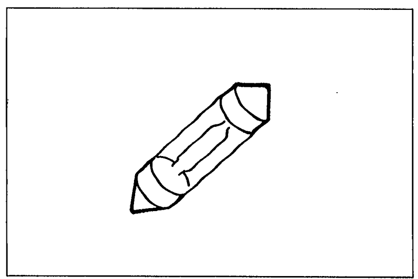
- 1Check the bulb of each lamp.
 05U0TX-180
 - 2If a bulb is burned, replace it.
- 3If the bulbs are OK, go to Step 4.
Step 4
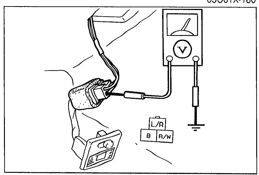
- 1Set the control switches to ON position.
 05U0TX-181
 - 2Measure the voltage at the following terminal-wires of each interior lamp connector.
Interior lamp connector — terminal-wire voltage check (Step 4)
(L/R)
Voltage12V
ActionNext check wire (B)
(L/R)
Voltage0V
ActionRepair wire (L/R) (ROOM 10A fuse—Interior lamp)
(B)
Voltage12V
ActionRepair wire (B) (Interior lamp—Body ground)
(B)
Voltage0V
ActionReplace interior lamp assembly
Step 5
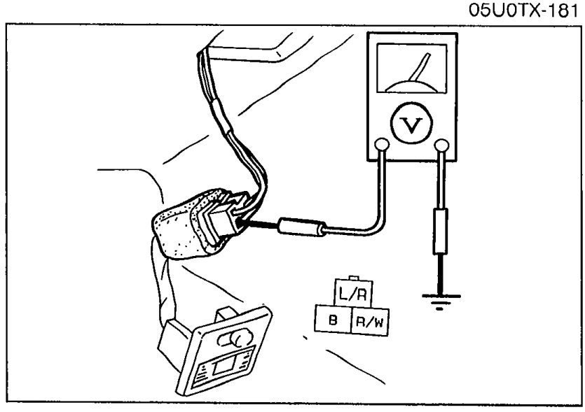
- 1Open both doors, and set the control switches to DOOR position.
 05U0TX-182
 - 2Measure the voltage at terminal-wire (R/W) of each interior lamp connector.
Interior lamp connector — (R/W) voltage check (Step 5)
(R/W)
Voltage12V
ActionGo to Step 6
(R/W)
Voltage0V
ActionReplace interior lamp assembly
Step 6
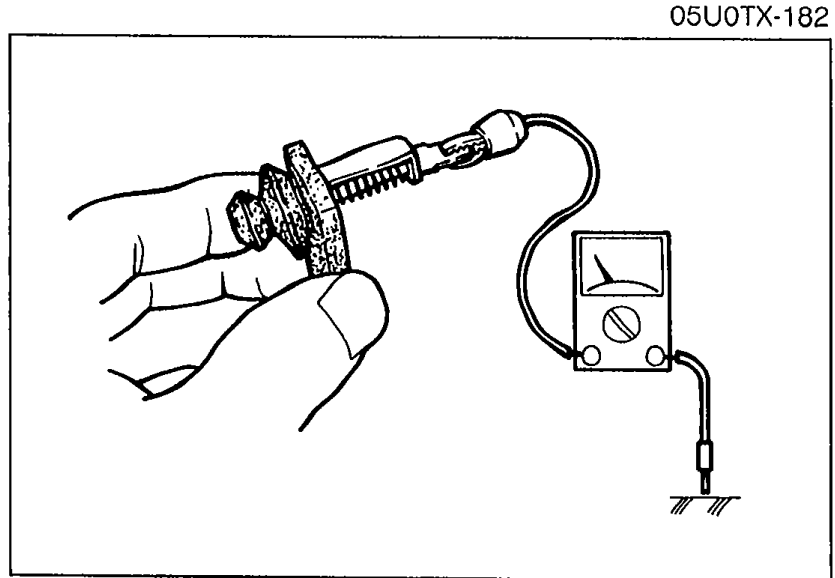
- 1Disconnect the door switch connector, and check continuity of each switch.
 05U0TX-183
Door switch continuity (Step 6)
Pushed
ContinuityNo
Released
ContinuityYes
Step 6 (continued)
- 2If not as specified, replace the door switch.
- 3If the switches are OK, repair wire (R/W). (Interior lamp-Door switch)
Step 7
- 1Set the control switches to ON position.
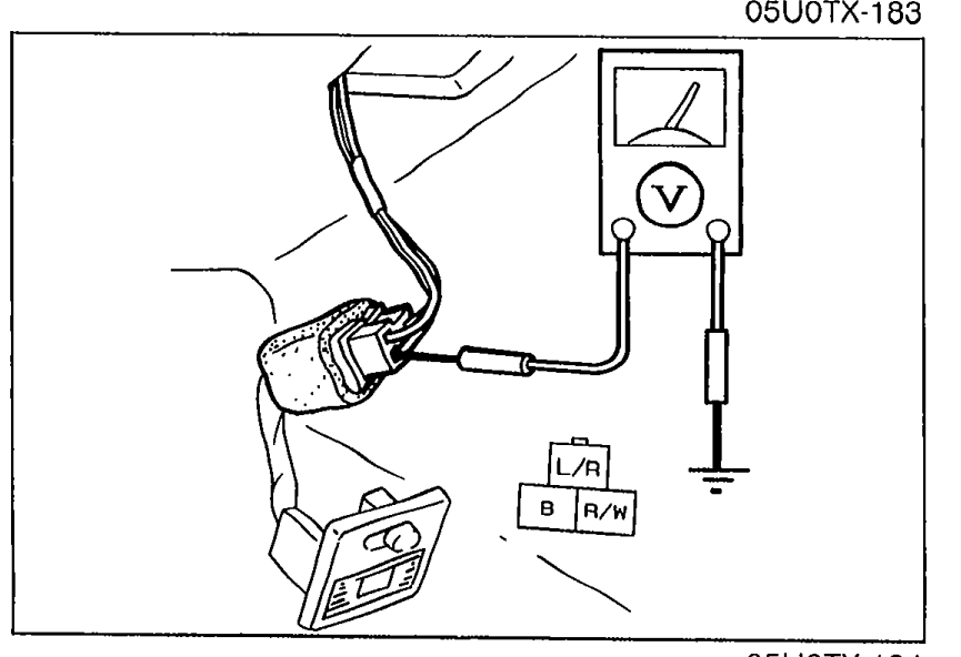 05U0TX-184
 - 2Measure the voltage at terminal-wire (B) of the interior lamp connector.
Interior lamp connector — (B) voltage check (Step 7)
(B)
Voltage12V
ActionRepair wire (B) (Interior lamp—Body ground)
(B)
Voltage0V
ActionReplace interior lamp assembly
See also
Step 4 · Step 6