
AUDIO - Symptom: Speaker(s) do not operate (With headrest speakers.)
T-117prose procedureProcedure applies to audio system with headrest speakers option.
Symptom: Speaker(s) do not operate (With headrest speakers.)
NOTE
Before troubleshooting, verify that the customer is using the audio system correctly. If not, advise or instruct him/her in the proper operating procedure. (Refer to page T-110.)
Step 1
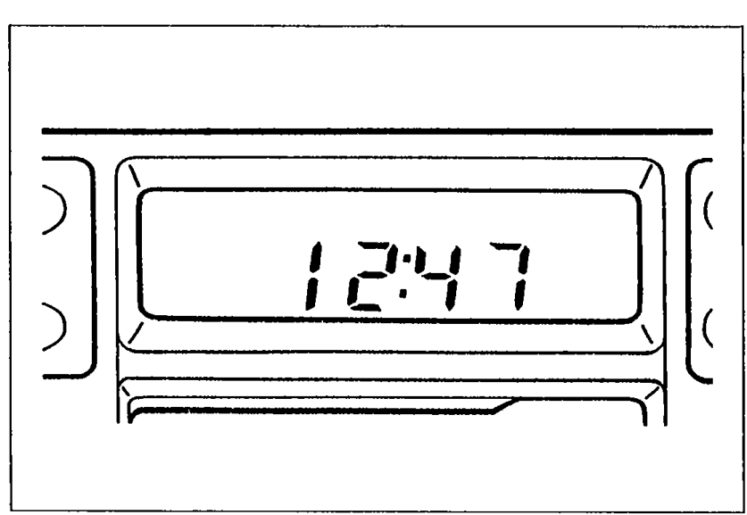
- 1Check if the anti-theft system has been activated. Turn the ignition switch to ACC and note the display.
 05U0TX-250
Step 1 - Display vs. Action
CODE flashes
ActionDeactive anti-theft system (Refer to page T-114.) Note: If CODE appears when ignition switch is turned to ACC from OFF go to Step 2.
Err flashes
ActionHave audio unit changed at a Panasonic service company
Clock
ActionGo to Step 4
No indication
ActionGo to Step 2
Step 2
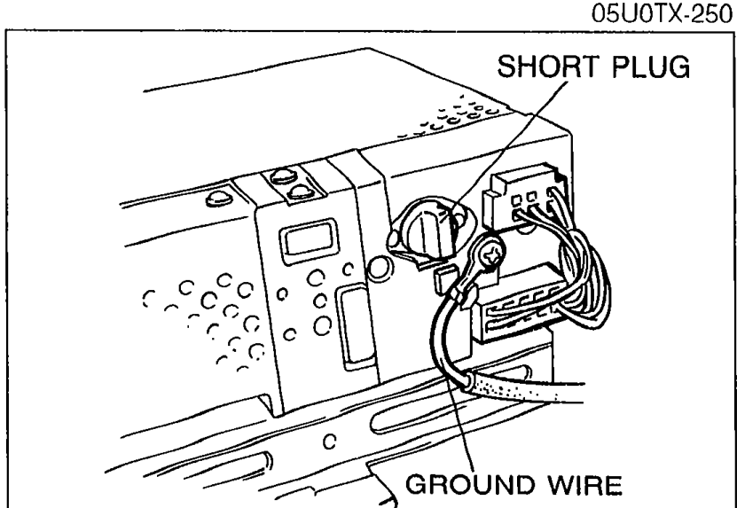
- 1Remove the audio unit. (Refer to page T-126.)
 05U0TX-251
 - 2Check the connections of the ground wire and the short plug.
- 3If a connection is poor or loose, repair or replace it.
- 4If the connections are OK, go to Step 3.
Step 3
- 1Turn the ignition switch to ACC.
 05U0TX-252
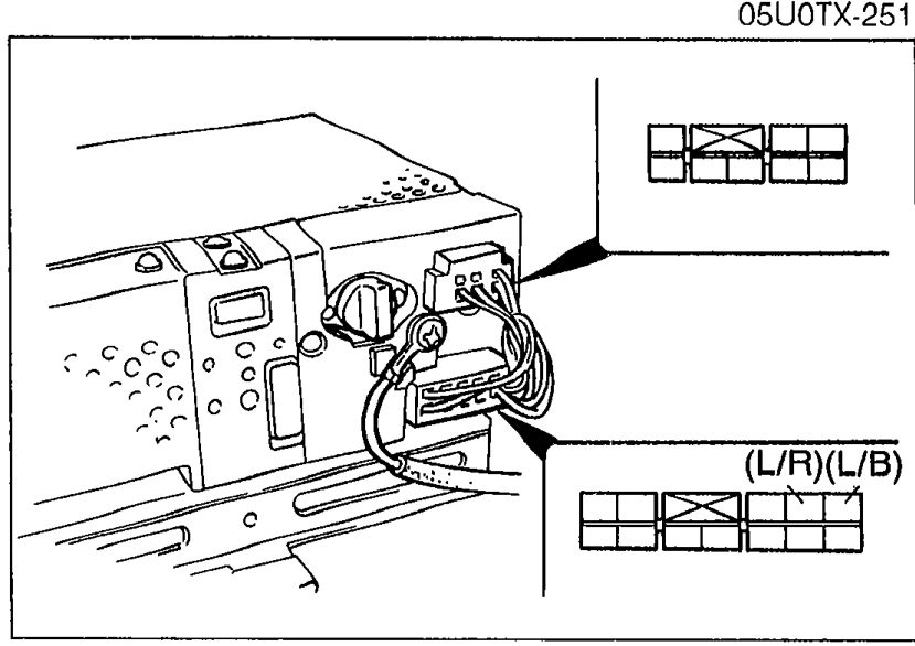
 - 2Measure the voltage at the following terminal-wires of the audio unit connector.
Step 3 - Voltage check at audio unit connector
(L/B)
Voltage12V
ActionNext, check wire (L/R)
(L/B)
Voltage0V
ActionCheck CIGAR 15A fuse. If CIGAR 15A fuse OK, repair wiring harness (CIGAR 15A fuse - Audio unit)
(L/R)
Voltage12V
ActionReplace audio unit
(L/R)
Voltage0V
ActionCheck ROOM 10A fuse. If ROOM 10A fuse OK, repair wiring harness (ROOM 10A fuse - Audio unit)
Step 4
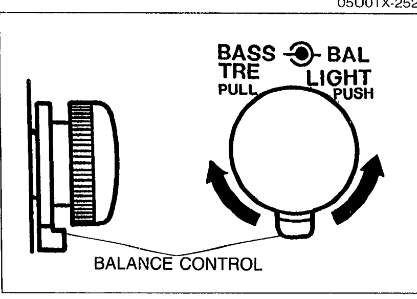
- 0Locate the faulty speaker(s) by using the headrest speaker volume, and balance control.
 05U0TX-259
 - 1Turn the ignition switch to ACC.
- 2Play a prerecorded tape, and set the volume to the center position.
- 3Set the head restraint speaker volume, and balance controls as shown in Table 2 (page T-118). Check operation of each speaker.
- 4From results of Table 2 testing, go to the next step.