
SWITCH
T-21prose procedureCaution notes apply to U.S. spec. Exploded view labelled Canada spec.
STEERING LOCK
Replacement
- 1Disconnect the negative battery cable.
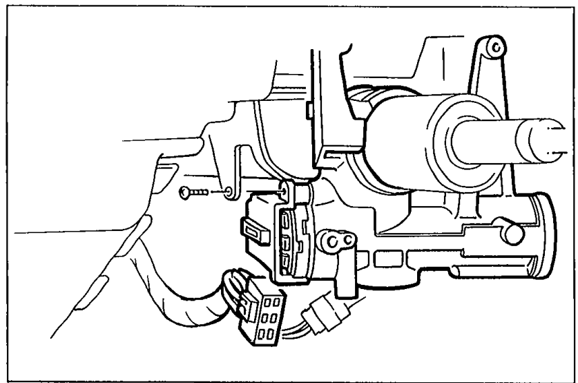 05U0TX-032
 - 2Remove the column covers.
- 3Remove the screw and the ignition switch.
- 4Install in the reverse order of removal.
Inspection
- 1Check continuity between terminals of the switch.
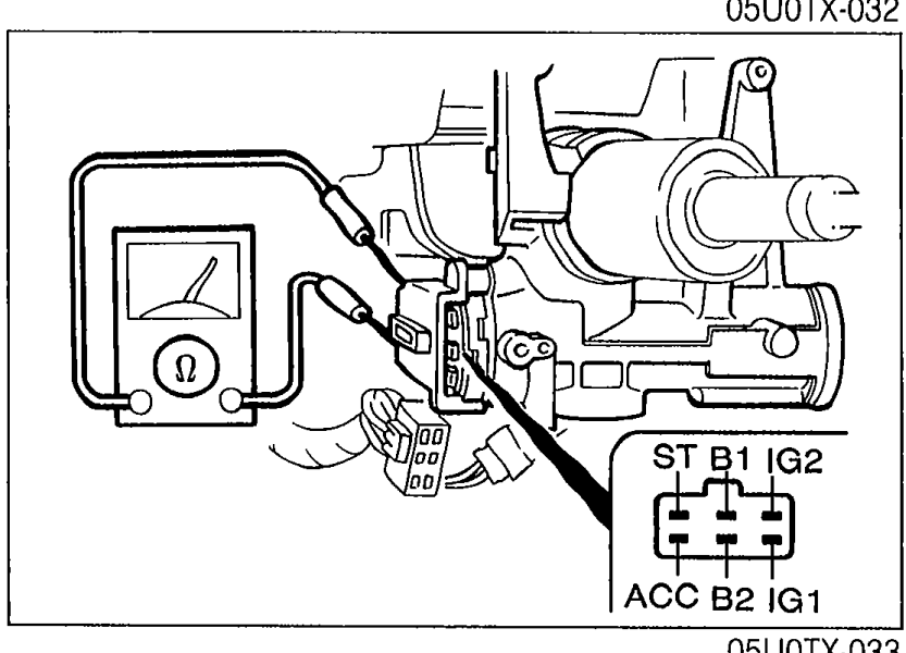 05U0TX-033
 - 2If not as specified, replace the combination switch.
Ignition Switch Continuity
LOCK
B1
B2
ACC
IG1
IG2
ST
K1O
K2O
ACC
B1
B2O
ACCO
IG1
IG2
ST
K1
K2
ON
B1O
B2O
ACCO
IG1O
IG2O
ST
K1
K2
START
B1O
B2
ACC
IG1O
IG2O
STO
K1
K2
NOTE
O—O : indicates continuity
COMBINATION SWITCH
Removal / Installation
CAUTION
Before removing the clock spring connector, disconnect the negative battery cable.
Before installing the steering wheel, reset the clock spring connector. (Refer to page T-22.)
Remove and install as shown in the figure.