
DRL troubleshooting: DRL do not operate (turn signals normal)
T-79prose procedureCanada-spec DRL troubleshooting.
IMPORTANT
Symptom: Daytime running lights (DRL) do not operate. (Turn signals function normally.)
NOTE
DRL operate with engine runing and following switches are off:
• Headlight switch
• Turn signal switch
• Hazard warning switch
• Parking brake switch (Parking brake released)
Step 1
- 1Turn on the ignition switch.Position the vehicle on a flat surface and block the wheels to prevent vehicle movement.
 05U0TX-157
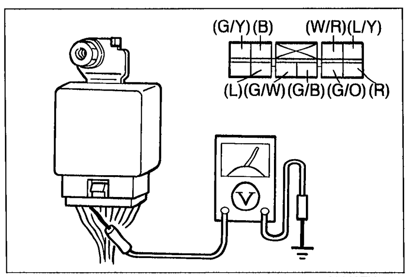
 - 2Measure the voltage at the following terminal-wires of the DRL unit.
- 3If correct, replace the DRL unit.
Step 1 DRL unit terminal voltage check
(L)
Connected toWIPER 20A fuse
Test conditionConstant
Specification12V
ActionRepair wire (L) (WIPER 20A—DRL unit)
(B)
Connected toGround
Test conditionConstant
Specification0V
ActionRepair wire (B) (DRL unit—Body ground)
(R)
Connected toParking brake switch
Test conditionParking brake released
Specification12V
ActionGo to Step 2
(W/R)
Connected toHeadlight switch
Test conditionHeadlight switch off
Specification0V
ActionGo to Step 3
Step 2
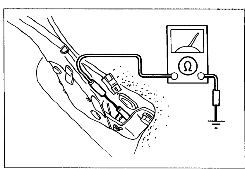
- 1Disconnect the parking brake switch connector.
 05U0TX-159
 - 2Check continuity between the terminal of the switch and a body ground.
- 3If not as specified, adjust or replace the parking brake switch.
- 4If correct, repair wires (R) and (L/Y). (Parking brake switch — DRL unit)
Step 2 Parking brake switch continuity
Pulled one notch
ContinuityYes
Released
ContinuityNo
Step 3
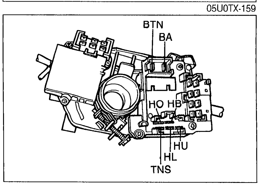
- 1Remove the column cover and disconnect the connectors of the headlight switch.
 05U0TX-160
 - 2Check continuity between the terminals of the headlight switch connector.
- 3If not as specified, replace the headlight switch.
- 4If correct, repair wire (W/R). (Headlight switch — DRL unit)
Step 3 Headlight switch continuity
Headlight switch ON
Terminal BTNO
Terminal TNSO
Headlight switch OFF
Terminal BTN
Terminal TNS
O—O: Indicates continuity