
AUDIO - Table 2 + Steps 5-7 (With headrest speakers)
T-118prose procedureApplies to audio system with optional headrest speakers (driver + passenger seat).
Table 2
Table 2 - Headrest-speaker balance/operation matrix
Left door
BalanceLeft
Head restraint speaker volumeMin
Speaker operatesYes
JudgementLeft door speaker circuit OK
Next Step-
Left door
BalanceLeft
Head restraint speaker volumeMin
Speaker operatesNo
JudgementLeft door speaker circuit faulty
Next StepStep 5
Right door
BalanceRight
Head restraint speaker volumeMin
Speaker operatesYes
JudgementRight door speaker circuit OK
Next Step-
Right door
BalanceRight
Head restraint speaker volumeMin
Speaker operatesNo
JudgementRight door speaker circuit faulty
Next StepStep 5
Left headrest (Driver seat)
Balance-
Head restraint speaker volumeMax
Speaker operatesYes
JudgementLeft headrest speaker circuit (driver seat) OK
Next Step-
Left headrest (Driver seat)
Balance-
Head restraint speaker volumeMax
Speaker operatesNo
JudgementLeft headrest speaker circuit (driver seat) faulty
Next StepStep 8
Right headrest (Driver seat)
Balance-
Head restraint speaker volumeMax
Speaker operatesYes
JudgementRight headrest speaker circuit (driver seat) OK
Next Step-
Right headrest (Driver seat)
Balance-
Head restraint speaker volumeMax
Speaker operatesNo
JudgementRight headrest speaker circuit (driver seat) faulty
Next StepStep 8
Left headrest (Passenger seat)
Balance-
Head restraint speaker volumeMax
Speaker operatesYes
JudgementLeft headrest speaker circuit (passenger seat) OK
Next Step-
Left headrest (Passenger seat)
Balance-
Head restraint speaker volumeMax
Speaker operatesNo
JudgementLeft headrest speaker circuit (passenger seat) faulty
Next StepStep 8
Right headrest (Passenger seat)
Balance-
Head restraint speaker volumeMax
Speaker operatesYes
JudgementRight headrest speaker circuit (passenger seat) OK
Next Step-
Right headrest (Passenger seat)
Balance-
Head restraint speaker volumeMax
Speaker operatesNo
JudgementRight headrest speaker circuit (passenger seat) faulty
Next StepStep 8
Step 5
- 1Remove the faulty door speaker cover and speaker installation screws.
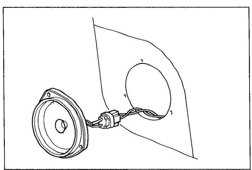 05U0TX-261
 - 2Check if the speaker is properly connected.
- 3If necessary, repair or reconnect the connector.
- 4If the connection is OK, go to Step 6.
Step 6
- 1Disconnect the connector from the suspected faulty speaker.
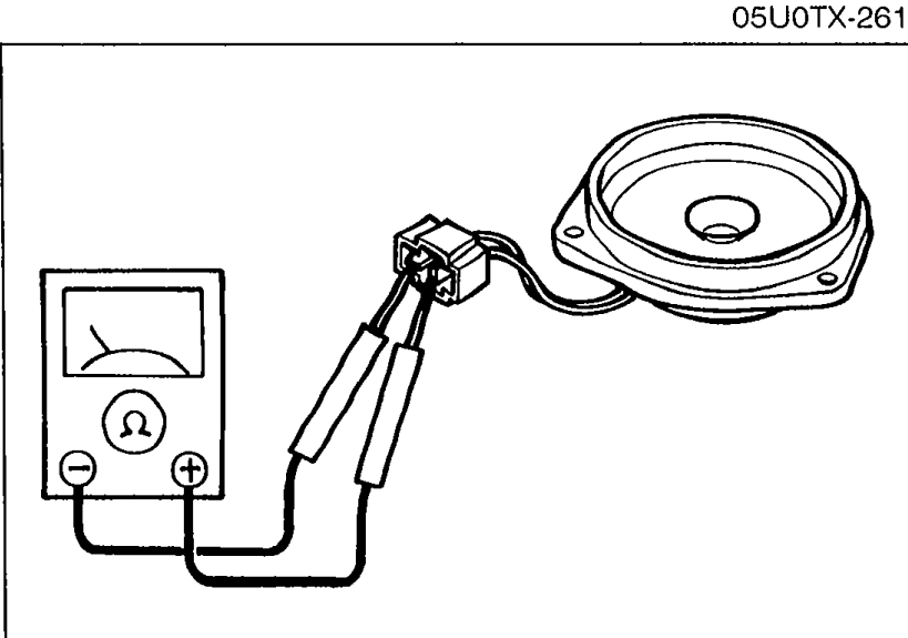 05U0TX-256
 - 2Measure resistance between terminals of the speaker.
- 3If not as specified, replace the speaker.Resistance: 4 ohm
- 4If the resistance is OK, go to Step 7.
| Specification | Value |
|---|---|
| Resistance | 4ohm |
Resistance
4ohm
Step 7
- 1Disconnect the 12-pin connector of the audio unit.
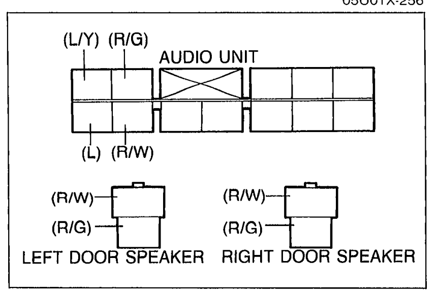 05U0TX-257
 - 2Disconnect both door speakers.
- 3Check for continuity of the following wires of the door speakers wire harness.
- 4If not as specified, repair the faulty wiring.
- 5If the wiring is OK, replace the audio unit.
Step 7 - Door speaker harness continuity
Audio unit - Left door speaker
Wire(R/W)
ContinuityYes
Audio unit - Left door speaker
Wire(R/G)
ContinuityYes
Audio unit - Right door speaker
Wire(L)
ContinuityYes
Audio unit - Right door speaker
Wire(L/Y)
ContinuityYes