
AIR BAG SYSTEM
T-148prose procedureFlowchart No. 7
Fault indication
DescriptionWarning lamp flashes two times or eight times
Possible cause
DescriptionPoor ground of D-sensor
CAUTION
Before troubleshooting, read SERVICE PRECAUTION on page T-133.
Step 1
- 1Disconnect the negative battery cable.
 05U0TX-401
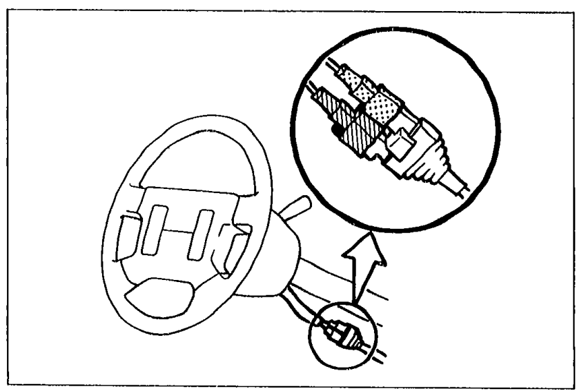
 - 2Remove the knee protector, and disconnect the clock spring connectors (Orange and blue).
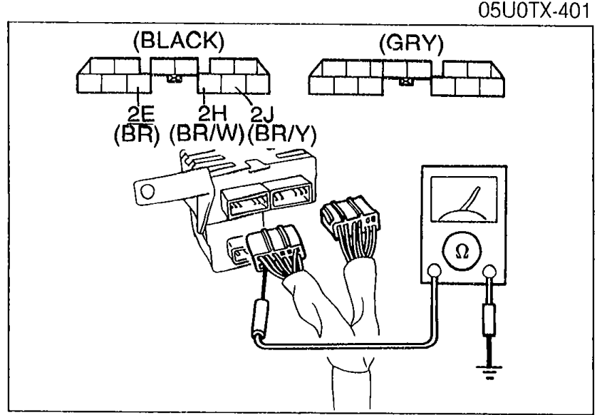
- 3Disconnect the diagnostic module connector.
 05U0TX-402
 - 4Check continuity between the following terminals of the diagnostic module connector and a body ground.
Step 1 — Diagnostic module terminal-wire to body ground continuity
2J (BR/Y)— Body ground
ContinuityYes
ActionNext, check between 2H (BR/W) and body ground
2J (BR/Y)— Body ground
ContinuityNo
ActionGo to Step 2
2H (BR/W)— Body ground
ContinuityYes
ActionNext, check between 2E (BR) and body ground
2H (BR/W)— Body ground
ContinuityNo
ActionGo to Step 3
2E (BR)— Body ground
ContinuityYes
ActionReplace diagnostic module
2E (BR)— Body ground
ContinuityNo
ActionGo to Step 4
Step 2
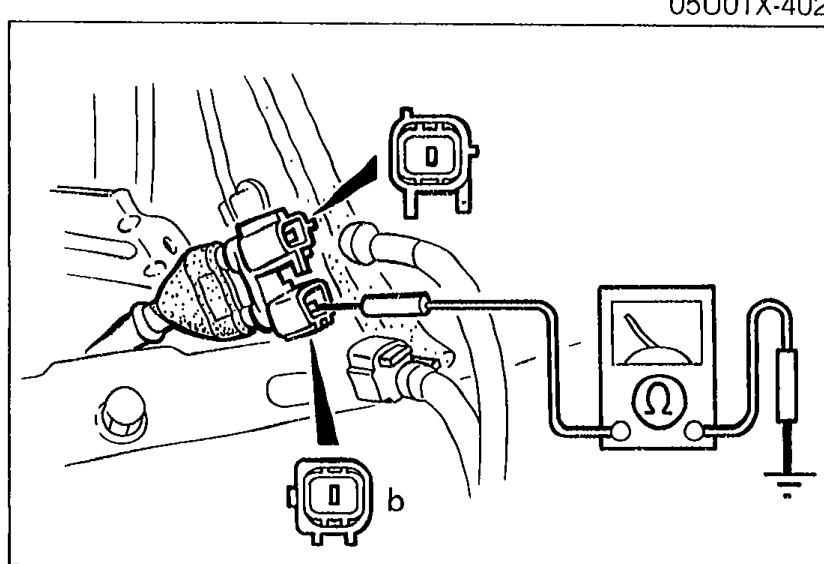
- 1Disconnect the D-sensor (RH) connectors, and check continuity between terminals of the sensor connectors and a body ground.
 05U0TX-403
 - 2If not as specified, go to Step 5.
- 3If correct, replace the wire harness assembly.
Step 2 — D-sensor (RH) terminal to body ground continuity
b—Body ground
ContinuityYes
Step 3
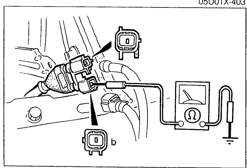
- 1Disconnect the D-sensor (CNT) connectors, and check continuity between terminals of the sensor connector and a body ground.
 05U0TX-404
 - 2If not as specified, go to Step 5.
- 3If correct, replace the wire harness assembly.
Step 3 — D-sensor (CNT) terminal to body ground continuity
b—Body ground
ContinuityYes